Quantcast
Channel: ENSDWI Training
Viewing all 193 articles
Browse latest View live

VLAN Trunking Questions 3

$
0
0

Here you will find answers to VLAN Trunking Questions – Part 3

Question 1

Which configuration option will cause the link between two Cisco 3600 Series Multiservice Platforms to become a functional trunk?

A. switchport dynamic auto switchport dynamic auto
B. switchport access vlan 10
switchport mode dynamic desirable
C. switchport mode trunk switchport nonegotiate
D. Leave both ports with the default trunk settings.


Answer: D

Question 2

If you were to set up a VLAN trunk over a Fast Ethernet link on switch R1, which trunk mode would you set the local port to on R1 if you wanted it to respond to requests from its link partner (R2) and become a trunk?

A. Auto
B. Negotiate
C. Designate
D. Nonegotiate


Answer: A

Question 3

Which two statements are true about best practices in VLAN design? (Choose two)

A. Routing should occur at the access layer if voice VLANs are utilized. Otherwise, routing should occur at the distribution layer.
B. Routing may be performed at all layers but is most commonly done at the core and distribution layers.
C. Routing should not be performed between VLANs located on separate switches.
D. VLANs should be local to a switch.
E. VLANs should be localized to a single switch unless voice VLANs are being utilized.


Answer: B D

Question 4

You need to configure a new Company switch to support DTP. Which DTP switchport mode parameter sets the switch port to actively send and respond to DTP negotiation frames?

A. Access
B. Nonegotiate
C. Trunk
D. Dynamic desirable
E. Dynamic auto


Answer: D


VLAN Trunking Questions 2

$
0
0

Here you will find answers to VLAN Trunking Questions – Part 2

Question 1

You are the network administrator at Company and switch R1 is configured as shown below:

interface GigabitEthernet0/1
switchport mode trunk
switchport trunk encapsulation dot1q
switchport trunk native vlan 5

If untagged frames are arriving on interface GigabitEthernet0/1 of R1, which of the following statement are correct?

A. Untagged frames are automatically assumed to be in VLAN 5.
B. Untagged frames are defaulted to VLAN 1 traffic.
C. Untagged frames are dropped because all packets are tagged when dot1q trunked.
D. Untagged frames are determined on the other switch
E. Untagged frames are not supported on 802.1Q trunks.


Answer: A

Explanation

The “switchport trunk native vlan 5″ sets VLAN 5 to be the native VLAN so traffic to this VLAN will be untagged. Also untagged traffic are automatically assumed to be in VLAN 5 -> A is correct.

Note: The native VLAN must match on both sides of the trunk link for 802.1Q; otherwise the link will not work.

Question 2

What are three results of issuing the “switchport host” command? (Choose three)

A. disables EtherChannel
B. enables port security
C. disables Cisco Discovery Protocol
D. enables PortFast
E. disables trunking
F. enables loopguard


Answer: A D E

Explanation

Catalyst 6500 switches running Cisco IOS software support the macro command switchport host. The switchport host macro command was designed to facilitate the configuration of switch ports that connect to end stations. Entering this command sets the switch port mode to access, enables spanning tree PortFast, and disables channel grouping, all at the same time. The switchport host macro command can be used as an alternative to the switchport mode access command.

(Reference: http://www.cisco.com/en/US/docs/solutions/Enterprise/Security/Baseline_Security/sec_chap7.html)

Question 3

If you were to configure an ISL Ethernet trunk between two Cisco switches, named R1 and R2, what would you have to include at the end of the link for the trunk to operate correctly? (Choose two)

A. An identical VTP mode.
B. An identical speed/duplex.
C. An identical trunk negotiation parameter.
D. An identical trunk encapsulation parameter.


Answer: B D

Explanation

One of the requirements for trunking to work is for speed and duplex to be the same on both sides. -> B is correct.

Maybe answer D wants to mention about encapsulation type (ISL or 802.1q) so it is an acceptable answer.

(Reference: http://www.cisco.com/en/US/products/hw/switches/ps663/products_configuration_example09186a008014859e.shtml)

Question 4

Which three statements are correct with regard to the IEEE 802.1Q standard? (Choose three)

A. The IEEE 802.1Q frame format adds a 4 byte field to a Ethernet frame
B. The packet is encapsulated with a 26 byte header and a 4 byte FCS
C. The protocol uses point-to-multipoint connectivity
D. The protocol uses point-to-point connectivity
E. The IEEE 802.1Q frame uses multicast destination of 0×01-00-0c-00-00
F. The IEEE 802.1Q frame retains the original MAC destination address


Answer: A D F

Explanation

There are two ways to implement Ethernet trunking:

* Inter-Switch Link Protocol (ISL, a Cisco proprietary protocol)
* 802.1Q (IEEE standard)

In Cisco implementation, a trunk is a point-to-point link, although it is possible to use the 802.1Q encapsulation on an Ethernet segment shared by more than two devices. Such a configuration is seldom needed but is still possible with the disablement of DTP negotiation -> D is correct.

IEEE 802.1Q uses an internal tagging mechanism which inserts a 4-byte tag field in the original Ethernet frame itself between the Source Address and Type/Length fields -> A is correct.

802_1q_frame_structure.jpg


The SA field is the source address field of the ISL packet. It is a 48-bit value -> F is correct.

(Reference: http://www.cisco.com/en/US/products/hw/switches/ps700/products_tech_note09186a008012ecf3.shtml)

Question 5

Refer to the exhibit. Why are users from VLAN 100 unable to ping users on VLAN 200?

Trunking_switch_router.jpg

A. Encapsulation on the switch is wrong.
B. Trunking needs to be enabled on Fa0/1.
C. The native VLAN is wrong.
D. VLAN 1 needs the no shutdown command.
E. IP routing needs to be enabled on the switch.


Answer: B

Explanation

In this question, maybe the exhibit forgot to describe Fa0/1 is the port on the switch which is connected to the router. To allow interVLAN routing between VLAN 100 and 200, this port must be configured as trunk port.

If you wish to see the full configuration of interVLAN routing, please read my interVLAN routing tutorial (you will see the configuration at the bottom of that tutorial).

Question 6

What is the effect of applying the “switchport trunk encapsulation dot1q” command to a port on a Cisco Catalyst switch?

A. By default, native VLAN packets going out this port will be tagged.
B. Without an encapsulation command, 802.1Q will be the default encapsulation if DTP fails to negotiate a trunking protocol.
C. The interface will support the reception of tagged and untagged traffic.
D. If the device connected to this port is not 802.1Q-enabled, it will not be able to handle 802.1Q packets.


Answer: C

Explanation

The “switchport trunk encapsulation dot1q” command configures trunk encapsulation as 802.1q, which supports the reception of tagged and untagged traffic -> C is correct.

Note: If your switch does not accept this command, try to enter “switchport” command first to configure the interface as a Layer 2 port.

Question 7

Two Company switches are connected via a trunk link. In this network, the original frame is encapsulated and an additional header is added before the frame is carried over a trunk link. At the receiving end, the header is removed and the frame is forwarded to the assigned VLAN. This describes which technology?

A. DISL
B. ISL
C. DTP
D. IEEE 802.1Q
E. MPLS


Answer: B

Explanation

Unlike 8021.q, ISL keeps the original frame unchanged. It only adds another header to that frame before sending out over a trunk link. For more information about this difference, please read the explanations of Question 2 and Question 3 in the first VLAN Trunking Questions part.

Question 8

Which of the following trunking modes are unable to request their ports to convert their links into trunk links? (Choose two)

A. Negotiate
B. Designate
C. Nonegotiate
D. Auto
E. Manual
F. Off


Answer: C D

Explanation

The mode auto (dynamic auto) causes the device not to send DTP Request but wait for DTP Request from neighboring device.

By using and switchport mode trunk and switchport nonegotiate commands, we can enable trunking to a device that does not support DTP. But notice that the switchport nonegotiate command causes the device not to send DTP Request frames.

Therefore both “auto” and “nonegotiate” modes makes the switch not to send request (which is “unable to convert their links into trunk links”) -> C and D are correct.

Question 9

show_interfaces_trunk_topology.jpg

You administer the network shown above. You issue the show interfaces trunk command on SwitchA and receive the following output:

show_interfaces_trunk_command.jpg

Which of the following statements is true regarding VLAN 32?

A. VLAN 32 is not allowed on the trunk port.
B. VLAN 32 is not active on the switch.
C. Traffic from VLAN 32 is not being sent over the trunk port.
D. Traffic from VLAN 32 is not restricted to only the trunk ports that require it.


Answer: C

Explanation

In the “Vlans allowed and active in management domain” VLAN 32 is not listed so we can conclude it is not active.

Question 10

Which statement is true regarding the configuration of ISL trunks?

A. A Catalyst switch cannot have ISL and IEEE 802.1q trunks enabled.
B. All Catalyst switches support ISL trunking.
C. A Catalyst switch will report giants if one side is configured for ISL while the other side is not.
D. ISL trunking requires that native VLANs match.


Answer: C

Explanation

First you should know “giant” frames are frames that exceed the maximum IEEE 802.3 frame size (usually greater then 1518 bytes). As you know, ISL does not modify the original Ethernet frame it received but it adds another outer header. In particular, it uses a 26 byte header and 4 byte FCS (30 bytes in total).

ISL Header
(26 bytes)
Encapsulation Frame (Original Data) FCS
(4 bytes)

But a normal Ethernet frame itself can have a maximum size of 1518 bytes. Therefore an Ethernet frame can be up to 1518 + 30 = 1548 bytes, which creates a “giant”.

That is why both ends must be configured as ISL trunks because only ISL-aware devices are able to read it.

VLAN Trunking Questions

$
0
0

Here you will find answers to VLAN Trunking Questions

Question 1

Which statement is correct about 802.1Q trunking?

A. Both switches must be in the same VTP domain.
B. The encapsulation type of both ends of the trunk does not have to match.
C. The native VLAN on both ends of the trunk must be VLAN 1.
D. 802.1Q trunking can only be configured on a Layer 2 port.
E. In 802.1Q trunking, all VLAN packets are tagged on the trunk link, except the native VLAN.


Answer: E

Explanation

By default frames from the native VLAN are not tagged. To force a switch to tag the native VLAN on all its 802.1Q trunks, we can use the following command:

Switch(config)#vlan dot1q tag native


Question 2

Which switch command enables a trunking protocol that appends a four byte CRC to the packet?

A. CompanySwitch(config-if)#switchport trunk encapsulation dot1q
B. CompanySwitch(config-if)#switchport trunk encapsulation itef
C. CompanySwitch(config-if)#switchport trunk encapsulation fddi
D. CompanySwitch(config-if)#switchport trunk encapsulation isl


Answer: D

Explanation

The ISL frame consists of three primary fields: the encapsulation frame (original frame), which is encapsulated by the ISL header, and the FCS at the end:

ISL Header Encapsulation Frame (Original Data) FCS

In ISL, the original frame is encapsulated and an additional header is added before the frame is carried over a trunk link. Also, a FCS is generated based on some fields in the ISL Header and the Encapsulation Frame and added to the end of the frame. At the receiving end, the header and FCS are removed and the frame is forwarded to the assigned VLAN. The FCS field consists of 4 bytes and contains a 32-bit CRC value.

Note: The addition of the new FCS does not alter the original FCS that is contained within the encapsulated frame.

Question 3

While using a packet analyzer, you notice four additional bytes being added to the packets in the Company network. Which protocol inserts a four byte tag into the Ethernet frame and recalculates CRC value?

A. DTP
B. VTP
C. 802.1Q
D. ISL


Answer: C

Explanation

802.1Q is the IEEE standard for tagging frames on a trunk and supports up to 4096 VLANs. In 802.1Q, the trunking device inserts a 4-byte tag into the original frame and recomputes the frame check sequence (FCS) before the device sends the frame over the trunk link. At the receiving end, the tag is removed and the frame is forwarded to the assigned VLAN. 802.1Q does not tag frames on the native VLAN.

Note: IEEE 802.1Q uses an internal tagging mechanism which inserts a 4-byte tag field in the original Ethernet frame itself.

(Reference: http://www.cisco.com/en/US/tech/tk389/tk689/technologies_tech_note09186a0080094665.shtml)

Note: From the Question 2 and Question 3 we can see a big difference in the way of using the FCS field in 802.1Q and ISL. 802.1Q modifies and FCS field inside the original Ethernet frame while ISL leaves the original FCS field inside the Ethernet frame unchanged, it just adds another FCS field outside the original Ethernet frame.

Therefore please pay attention to which question is asked. Question 2 asks “appends a four byte CRC to the packet” which means ISL while Question 3 says “inserts a four byte tag into the Ethernet frame” which means 802.1Q.

Question 4

Which statement is correct about 802.1Q trunking?

A. Both switches must be in the same VTP domain.
B. The encapsulation type of both ends of the trunk does not have to match.
C. The native VLAN on both ends of the trunk must be VLAN 1.
D. 802.1Q trunking can only be configured on a Layer 2 port.
E. In 802.1Q trunking, all VLAN packets are tagged on the trunk link, except the native VLAN.


Answer: E

Question 5

Which command alone will disable trunking on a Layer 2 switch port?

A. no switchport trunk native vlan vlan-id
B. switchport nonegotiate
C. no switchport mode dynamic desirable
D. switchport mode access


Answer: D

Explanation

The “switchport mode access” command forces a switch port to always behave as an access port (with no capability of establishing trunks).

Note: When using the switchport nonegotiate command, Dynamic Inter-Switch Link Protocol and Dynamic Trunking Protocol (DISL/DTP)-negotiation packets are not sent on the interface. The device trunks or does not trunk according to the mode parameter given: access or trunk.


Question 6

ISL is being configured on a Company switch. Which of the following choices are true regarding the ISL protocol? (Choose two)

A. It can be used between Cisco and non-Cisco switch devices.
B. It calculates a new CRC field on top of the existing CRC field.
C. It adds 4 bytes of protocol-specific information to the original Ethernet frame.
D. It adds 30 bytes of protocol-specific information to the original Ethernet frame.


Answer: B D

Explanation

ISL encapsulates the entire Ethernet frame (Fast Ethernet or Gigabit Ethernet) with a 26-byte header and a 4-byte frame check sequence (FCS) for a total of 30 bytes of overhead.

ISL Header
(26 bytes)
Encapsulation Frame (Original Data) FCS
(4 bytes)

Question 7

A new Company switch was just configured using the “switchport trunk native vlan 7″ command. What does this interface command accomplish?

A. Causes the interface to apply ISL framing for traffic on VLAN 7
B. Configures the trunking interface to forward traffic from VLAN 7
C. Configures the interface to be a trunking port and causes traffic on VLAN 7 to be 802.1q tagged
D. Configures the trunking interface to send traffic from VLAN 7 untagged


Answer: D

Explanation

The “switchport trunk native vlan 7″ sets VLAN 7 to be the native VLAN so traffic to this VLAN will be untagged. Also untagged traffic are automatically assumed to be in VLAN 7 -> D is correct.

Question 8

If you needed to transport traffic coming from multiple VLANs (connected between switches), and your CTO was insistent on using an open standard, which protocol would you use?

A. 802.11B
B. spanning-tree
C. 802.1Q
D. ISL
E. VTP
F. Q.921


Answer: C

Explanation

IEEE’s 802.1Q VLAN tagging is the industry standard to carry traffic for multiple VLANs on a single trunking interface between two Ethernet switches while Inter-Switch Link (ISL) is a Cisco proprietary VLAN tagging protocol.

Question 9

The Company core switches use 802.1Q trunks to connect to each other. How does 802.1Q trunking keep track of multiple VLANs?

A. It tags the data frame with VLAN information and recalculates the CRC value
B. It encapsulates the data frame with a new header and frame check sequence
C. It modifies the port index of a data frame to indicate the VLAN
D. It adds a new header containing the VLAN ID to the data frame


Answer: A

Explanation

IEEE 802.1Q uses an internal tagging mechanism which inserts a 4-byte tag field in the original Ethernet frame itself between the Source Address and Type/Length fields. This tag includes VLAN information (12 bits) to distinguish between VLANs on the link.

802_1q_frame_structure.jpg

Question 10

You are the network administrator tasked with designing a switching solution for the Company network. Which of the following statements describing trunk links are INCORRECT? (Choose four)

A. The trunk link belongs to a specific VLAN.
B. Multiple trunk links are used to connect multiple end user devices.
C. A trunk link only supports native VLAN.
D. Trunk links use 802.10 to identify a VLAN.
E. The native VLAN of the trunk link is the VLAN that the trunk uses for untagged packets.


Answer: A B C D


VLAN Questions 3

$
0
0

Here you will find answers to VLAN Questions – Part 3

Question 1

Refer to the exhibit. On the basis of the output generated by the show commands, which two statements are true? (Choose two)

show_interface_gigabitethernet_show_vlan.jpg

A. Interface gigabitethernet 0/1 has been configured as Layer 3 ports.
B. Interface gigabitethernet 0/1 does not appear in the show vlan output because switchport is enabled.
C. Interface gigabitethernet 0/1 does not appear in the show vlan output because it is configured as a trunk interface.
D. VLAN2 has been configured as the native VLAN for the 802.1q trunk on interface gigabitethernet 0/1.
E. Traffic on VLAN 1 that is sent out gigabitethernet 0/1 will have an 802.1q header applied.
F. Traffic on VLAN 2 that is sent out gigabitethernet 0/1 will have an 802.1q header applied.


Answer: C F

Explanation

From the output of show interface gigabitethernet 0/1 switchport command we can see this port is currently configured as trunked port (Operational Mode: trunk) and uses 802.1q encapsulation. So surely the “show vlan” command will not list this port -> C is correct.

Also from the first output we learned the native VLAN is VLAN 1 (Trunking Native Mode VLAN:1) so only traffic from this VLAN is sent untagged -> traffic sent from VLAN 2 out this port will have an 802.1q header applied -> F is correct.

Question 2

When you issue a command show port 3/1 on an Ethernet port, you observe the ‘Giants’ column has a non-zero entry. What could cause of this?

A. IEEE 802.1Q
B. IEEE 802.10
C. Misconfigured NIC
D. User configuration
E. All of the above


Answer: A

Explanation

Generally, frames that are greater than 1522 bytes are categorized as giant frames (notice that a normal Ethernet frame has a size that ranges from 64 bytes to 1518 bytes). Giant frames often are the result of some protocol-tagging mechanisms, for example 802.1Q frames (1522 bytes), MPLS (1518 + 4 * n, where n is the number of stacked labels), ISL frames (1548 bytes).

There are nothing wrong with giant frames, just make sure you configure both end devices to support these frames.

Note: In fact, frames that are created by 802.1Q are often known as baby giants (frames that are slightly larger than 1518 bytes).

Question 3

You want to configure a switched internetwork with multiple VLANs as shown above. Which of the following commands should you issue on SwitchA for the port connected to SwitchB?

switchport_mode_trunk.jpg

A. switchport mode trunk
B. switchport access vlan 5
C. switchport mode access vlan 5
D. switchport trunk native vlan 5


Answer: A

Explanation

To support interVLAN routing, the links between two switches must be configured as trunk link.

Question 4

Refer to the exhibit. VLAN 1 and VLAN 2 are configured on the trunked links between Switch A and Switch B. Port Fa 0/2 on Switch B is currently in a blocking state for both VLANs. What should be done to load balance VLAN traffic between Switch A and Switch B?

trunk_blocking_state.jpg

A. Lower the port priority for VLAN 1 on port 0/1 for Switch A.
B. Lower the port priority for VLAN 1 on port 0/2 for Switch A.
C. Make the bridge ID of Switch B lower than the ID of Switch A.
D. Enable HSRP on the access ports.


Answer: B

Explanation

Please read the explanation of Question 1 in http://www.certprepare.com/vlan-vtp-stp-questions.

In general, lower the port priority for VLAN 1 will lower the Root Bridge ID for port Fa0/2 on Switch A -> traffic for VLAN 1 will flow via Fa0/2 link.

Question 5

On a multilayer Catalyst switch, which interface command is used to convert a Layer 3 interface to a Layer 2 interface?

A. switchport access vlan vlan-id
B. switchport
C. switchport mode access
D. no switchport


Answer: B

Question 6

Refer to the exhibit and the show interfaces fastethernet0/1 switchport outputs. Users in VLAN 5 on switch SW_A complain that they do not have connectivity to the users in VLAN 5 on switch SW_B. What should be done to fix the problem?

show_interfaces_fastethernet_switchport_switch.jpg

A. Configure the same number of VLANs on both switches.
B. Create switch virtual interfaces (SVI) on both switches to route the traffic.
C. Define VLAN 5 in the allowed list for the trunk port on SW_A.
D. Disable pruning for all VLANs in both switches.
E. Define VLAN 5 in the allowed list for the trunk port on SW_B.


Answer: C

Explanation

SW_A is missing VLAN 5 in the “Trunking VLANs Enabled”, that means the trunk link currently does not accept traffic from VLAN 5 to be sent on the link.

Question 7

Refer to the show interface Gi0/1 switchport command output shown in the exhibit. Which two statements are true about this interface? (Choose two)

show_interface_gigabitethernet_access.jpg

A. This interface is a member of a voice VLAN.
B. This interface is configured for access mode.
C. This interface is a dot1q trunk passing all configured VLANs.
D. This interface is a member of VLAN 7.
E. This interface is a member of VLAN 1.


Answer: B D

Question 8

In the three-layer hierarchical network design model; what’s associated with the access layer? (Choose two)

A. optimized transport structure
B. high port density
C. boundary definition
D. data encryption
E. local VLANs
F. route summaries


Answer: B E

Explanation

Main characteristics of three layers in the three-layer hierarchical network design model:

* Access layer:
+ Low cost per switch port
+ High port density
+ Scalable uplinks to higher layers
+ User access functions such as VLAN membership, traffic and protocol filtering, and quality of service (QoS)
+ Resiliency through multiple uplinks

* Distribution Layer:
+ Aggregation of multiple access-layer devices
+ High Layer 3 throughput for packet handling
+ Security and policy-based connectivity functions through access lists or packet filters
+ QoS features
+ Scalable and resilient high-speed links to the core and access layers

* Core layer:
+ Very high throughput at Layer 3
+ No costly or unnecessary packet manipulations (access lists, packet filtering)
+ Redundancy and resilience for high availability
+ Advanced QoS functions

Also, end-to-end VLANs and local VLANs belong to access layer.

Question 9

Refer to the following exhibits:

Exhibit #1

show_interfaces_fastethernet_switchport_dynamic_auto.jpg

Exhibit #2

show_interfaces_fastethernet_switchport_dynamic_desirable.jpg

Study the exhibits carefully. The switchport output in Exhibit #1 displays the default settings of interface FastEthernet 0/13 on switch Sw1. Figure 2 displays the desired interface settings. Which command sequence would configure interface FastEthernet 0/13 as displayed in Exhibit #2?

A.
Sw1(config-if)# switchport trunk encapsulation dot1q
Sw1 (config-if)# switchport mode dynamic auto
Sw1 (config-if)# switchport trunk native DATA
Sw1 (config-if)# switchport trunk allowed vlan add 1,10,20

B.
Sw1(config-if)# switchport trunk encapsulation dot1q
Sw1(config-if)# switchport mode dynamic desirable
Sw1(config-if)# switchport trunk native vlan DATA
Sw1(config-if)# switchport trunk allowed vlan 1,10,20

C.
Sw1 (config-if)# switchport trunk encapsulation dot1q
Sw1 (config-if)# switchport mode trunk
Sw1 (config-if)# switchport trunk native DATA
Sw1 (config-if)# switchport trunk allowed vlan 1,10,20

D.
Sw1(config-if)# switchport trunk encapsulation dot1q
Sw1(config-if)#switchport mode dynamic desirable
Sw1(config-if)#switchport trunk native vlan 10

E.
Sw1 (config-if)# switchport trunk encapsulation dot1q
Sw1 (config-if)# switchport mode dynamic desirable
Sw1 (config-if)# switchport trunk native vlan 10
Sw1 (config-if)# switchport trunk allowed vlan 1,10,20


Answer: E

VLAN Questions 2

$
0
0

Here you will find answers to VLAN Questions – Part 2

Question 1

Refer to the exhibit. Based upon the output of show vlan on switch CAT2, what can we conclude about interfaces Fa0/13 and Fa0/14?

show_vlan.jpg

A. That interfaces Fa0/13 and Fa0/14 are in VLAN 1
B. That interfaces Fa0/13 and Fa0/14 are down
C. That interfaces Fa0/13 and Fa0/14 are trunk interfaces
D. That interfaces Fa0/13 and Fa0/14 have a domain mismatch with another switch
E. That interfaces Fa0/13 and Fa0/14 have a duplex mismatch with another switch


Answer: C

Explanation

Trunk ports are part of multiple VLANs, not of just a single VLAN so they never show up in the show vlan command. You can check the trunk port with the show interfaces trunk or show interface {port} switchport command. You can find an example output of this command in Question 8.

Note: Trunk ports that are not connected appear by default in vlan 1 and also appear in the output of the show vlan command.

Question 2

What two pieces of information will the show vlan id 5 command display? (Choose two)

A. Ports in VLAN 5
B. Utilization
C. VLAN information on port 0/5
D. Filters
E. MTU and type


Answer: A E

Explanation

The show vlan id vlan-id command display information about a particular VLAN. But notice that this command will also list trunk ports that allow this VLAN to run on. An example of the “show vlan id” command is shown below:

show_vlan_id.jpg

Question 3

What are some virtues of implementing end-to-end VLANs? (Choose two)

A. End-to-end VLANs are easy to manage.
B. Users are grouped into VLANs independent of a physical location.
C. Each VLAN has a common set of security and resource requirements for all members.
D. Resources are restricted to a single location.


Answer: B C

Explanation

There are two kinds of VLANs:

* End-to-end VLANs: also called campuswide VLANs, span the entire switch fabric of a network. They are positioned to support maximum flexibility and mobility of end devices. Users can be assigned to VLANs regardless of their physical location. As a user moves around the campus, that user’s VLAN membership stays the same. End-to-end VLANs should group users according to common requirements. All users in a VLAN should have roughly the same traffic flow patterns

* Local VLANs: based on geographic locations by demarcation at a hierarchical boundary (core, distribution, access)

(Reference: CCNP SWITCH 642-813 Official Certification Guide)

Question 4

Which two statements are true about a switched virtual interface (SVI)? (Choose two)

A. An SVI is created by entering the no switchport command in interface configuration mode.
B. An SVI is normally created for the default VLAN (VLAN1) to permit remote switch administration.
C. An SVI provides a default gateway for a VLAN.
D. Multiple SVIs can be associated with a VLAN.
E. SVI is another name for a routed port.


Answer: B C

Explanation

Catalyst L2 fixed configuration switches that run Cisco IOS Software have only one configurable IP management interface, which by default is interface VLAN 1. Pure layer 2 switches can have only one interface VLAN up at the time. This is called the management VLAN (in IOS) or the sc0 interface (in CatOS). The main purpose of this interface is management (telnet, SNMP, etc). If the switch is a Layer 3 switch, you can configure multiple VLANs and route between them. An L3 switch can handle multiple IPs, so there is no specific management VLAN on the switch.

(Reference: http://www.cisco.com/en/US/products/hw/switches/ps708/products_tech_note09186a008010e9ca.shtml)

Question 5

You have just created a new VLAN on your network. What is one step that you should include in your VLAN based implementation and verification plan?

A. Verify that trunked links are configured to allow the VLAN traffic.
B. Verify that the switch is configured to allow for trunking on the switch ports.
C. Verify that each switch port has the correct IP address space assigned to it for the new VLAN.
D. Verify that different native VLANs exist between two switches for security purposes.


Answer: A

Explanation

A VLAN-based implementation and verification plan should include:

* Verification that trunked links are configured to allow the newly created VLANs.
* Verification that the SVI has already been created and that it shows up on all required switches using the show vlan command.

Question 6

You have just created a new VLAN on your network for inter-VLAN routing. What is one step that you should include in your VLAN-based implementation and verification plan?

A. Verify that different native VLANs exist between two switches for security purposes.
B. Verify that the switch is configured to allow for trunking on the switch ports.
C. Verify that each switch port has the proper IP address space assigned to it for the new VLAN.
D. Verify that the VLAN virtual interface has been correctly created and enabled.


Answer: D

Explanation

Same as Question 5.

Question 7

Under what circumstances should an administrator prefer local VLANs over end-to-end VLANs?

A. Eighty percent of traffic on the network is destined for Internet sites.
B. There are common sets of traffic filtering requirements for workgroups located in multiple buildings.
C. Eighty percent of a workgroup’s traffic is to the workgroup’s own local server.
D. Users are grouped into VLANs independent of physical location.


Answer: A

Explanation

End-to-end VLAN follows the 80/20 rule in which 80 percent of user traffic stays within the local workgroup, whereas 20 percent is destined for a remote resource in the campus network (like Internet…).

In contrast to end-to-end-VLAN, local VLAN follows the 20/80 rule: only 20 percent of traffic is local, whereas 80 percent is destined to a remote re-source across the core layer -> A is correct.

(Reference: CCNP SWITCH 642-813 Official Certification Guide)

Question 8

Which of the following statements is true about the 80/20 rule (Choose two)?

A. 20 percent of the traffic on a network segment should be local.
B. no more than 20 percent of the network traffic should be able to move across a backbone.
C. no more than 80 percent of the network traffic should be able to move across a backbone.
D. 80 percent of the traffic on a network segment should be local.


Answer: B D

Explanation

The 80/20 rule states that 80 percent of user traffic stays within the local workgroup, whereas 20 percent is destined for a remote resource in the campus network


Question 9

Which two statements are true about best practices in VLAN design? (Choose two.)

A. Routing should occur at the access layer if voice VLANs are utilized. Otherwise, routing should occur at the distribution layer.
B. Routing may be performed at all layers but is most commonly done at the core and distribution layers.
C. Routing should not be performed between VLANs located on separate switches.
D. VLANs should be local to a switch.
E. VLANs should be localized to a single switch unless voice VLANs are being utilized.


Answer: B D

Explanation

First let’s review main characteristics of three layers in a campus network:

* Access layer:

+ Low cost per switch port
+ High port density
+ Scalable uplinks to higher layers
+ User access functions such as VLAN membership, traffic and protocol filtering, and quality of service (QoS)
+ Resiliency through multiple uplinks

* Distribution Layer:

+ Aggregation of multiple access-layer devices
+ High Layer 3 throughput for packet handling
+ Security and policy-based connectivity functions through access lists or packet filters
+ QoS features
+ Scalable and resilient high-speed links to the core and access layers

* Core layer:

+ Very high throughput at Layer 3
+ No costly or unnecessary packet manipulations (access lists, packet filtering)
+ Redundancy and resilience for high availability
+ Advanced QoS functions

We can see at Distribution and Core layers, Layer 3 throughput (routing) is very high -> B is correct.

Nowadays, end-to-end VLANs are not recommended in an enterprise network, unless there is a good reason. In an end-to-end VLAN, broadcast traffic is carried over from one end of the network to the other, creating the possibility for a broadcast storm or Layer 2 bridging
loop to spread across the whole extent of a VLAN. This can exhaust the bandwidth of distribution and core-layer links, as well as switch CPU resources. Now the storm or loop has disrupted users on the end-to-end VLAN, in addition to users on other VLANs that might
be crossing the core.

When such a problem occurs, troubleshooting becomes more difficult. In other words, the risks of end-to-end VLANs outweigh the convenience and benefits.

From that we can infer VLAN traffic should be local to the switch -> D is correct.

(Reference: CCNP SWITCH 642-813 Official Certification Guide)

Question 10

show_interfaces_fastethernet_switchport.jpg

Refer to the exhibit. The user who is connected to interface FastEthernet 0/1 is on VLAN 10 and cannot access network resources. On the basis of the information in the exhibit, which command sequence would correct the problem?

A. SW1(config)# vlan 10
SW1(config-vlan)# no shut

B. SW1(config)# interface fastethernet 0/1
SW1(config-if)# switchport mode access
SW1(config-if)# switchport access vlan 10

C. SW1(config)# interface fastethernet 0/1
SW1(config-if)# switchport mode access

D. SW1(config)# vlan 10
SW1(config-vlan)# state active

E. SW1(config)# interface fastethernet 0/1
SW1(config-if)# no shut


Answer: E


VLAN Questions

$
0
0

Here you will find answers to VLAN Questions

Question 1

You are assigning VLANs to the ports of switch R1. What VLAN number value is an assigned to the default VLAN?

A VLAN 1003
B. VLAN 1
C. VLAN ON
D. VLAN A
E. VLAN 0


Answer: B

Question 2

What is a characteristic of a static VLAN membership assignment?

A. VMPS server lookup is required
B. Easy to configure
C. Ease of adds, moves, and changes
D. Based on MAC address of the connected device


Answer: B

Explanation

There are two types of VLAN membership assignment:

* Static VLAN: switch ports are assigned to specific VLANs manually

* Dynamic VLAN: switch automatically assigns the port to a VLAN using information from the user device like MAC address, IP address etc. When a device is connected to a switch port, the switch must, in effect, query a database to establish VLAN membership.

Static VLAN assignment provides a simple way to assign VLAN to a port while Dynamic VLANs allow a great deal of flexibility and mobility for end users but require more administrative overhead.

Question 3

What is a characteristic of multi-VLAN access ports?

A. The port has to support STP PortFast.
B. The auxiliary VLAN is for data service and is identified by the PVID.
C. The port hardware is set as an 802.1Q trunk.
D. Both the voice service and data service use the same trust boundary.


Answer: C

Explanation

The multi-VLAN port feature on the Catalyst 2900 XL/3500 XL switches allows for configuring a single port in two or more VLANs. This feature allows users from different VLANs to access a server or router without implementing InterVLAN routing capability. A multi-VLAN port performs normal switching functions in all its assigned VLANs. VLAN traffic on the multi-VLAN port is not encapsulated as it is in trunking -> The port is set as an 802.1Q trunk -> C is correct.

Note: The limitations of implementing multi-VLAN port features are listed below.

1) You cannot configure a multi-VLAN port when a trunk is configured on the switch. You must connect the multi-VLAN port only to a router or server. The switch automatically transitions to VTP transparent mode when the multi-VLAN port feature is enabled, making the VTP disabled.

2) The multi-VLAN port feature is supported only on the Catalyst 2900 XL/3500 XL series switches. This feature is not supported on the Catalyst 4000/5000/6000 series or any other Cisco Catalyst switches.

The following example shows how to configure a port for multi-VLAN mode:
Switch(config-if)# switchport mode multi

The following example shows how to assign a multi-VLAN port already in multi mode to a range of VLANs:
Switch(config-if)# switchport multi vlan 5-10

Question 4

The Company LAN switches are being configured to support the use of Dynamic VLANs. Which of the following are true of dynamic VLAN membership? (Choose two)

A. VLAN membership of a user always remains the same even when he/she is moved to another location.
B. VLAN membership of a user always changes when he/she is moved to another location.
C. Membership can be static or dynamic.
D. Membership can be static only.


Answer: A C

Explanation

Please read the explanation of Question 2

Question 5

Which of the following technologies would an Internet Service Provider use to support overlapping customer VLAN ID’s over transparent LAN services?

A. 802.1q tunneling
B. ATM
C. SDH
D. IP Over Optical Networking
E. ISL


Answer: A

Explanation

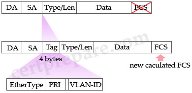
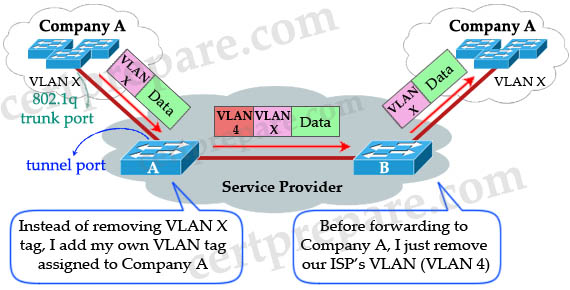
Using the IEEE 802.1Q tunneling (QinQ) feature, service providers can use a single VLAN to support customers who have multiple VLANs. The trick here is instead of removing the VLAN tag received from customers, the ISP’s edge switch puts that traffic into the VLAN assigned to that port and adds another VLAN tag outside that tag. Let’s see an example:

802_1q_tunneling_QinQ.jpg

When Switch A (of the Service Provider) receives customer traffic from an 802.1Q trunk port, it does not strip the received 802.1Q tag from the frame header; instead, the tunnel port leaves the 802.1Q tag intact, adds a 1-byte Ethertype field (0×8100) and a 1-byte length field and puts the received customer traffic into the VLAN to which the tunnel port is assigned. This Ethertype 0×8100 traffic, with the received 802.1Q tag intact, is called tunnel traffic. Notice that “VLAN X” here can be one or multiple VLANs, all will be tagged with VLAN 4 (suppose VLAN 4 is assigned to Company A).

A benefit of 802.1qQ tunneling is multiple companies can use the overlapped VLANs. For example, Company A can use VLANs 1 to 100 while Company B can use VLANs 50 to 100 (overlapped from VLANs 50 to 100). The ISP’s switches can still classify them because they are attached to different outer VLAN tags. In the example above Company A is assigned to VLAN 4 so we can assign Company B to VLAN 5, Company C to VLAN 6 and so on.

The link between the 802.1Q trunk port on a customer device and the tunnel port is called an asymmetrical link because one end is configured as an 802.1Q trunk port and the other end is configured as a tunnel port.

Note: By default, the native VLAN traffic of a dot1q trunk is sent untagged, which cannot be double-tagged in the service provider network. Because of this situation, the native VLAN traffic might not be tunneled correctly. Be sure that the native VLAN traffic is always sent tagged in an asymmetrical link. To tag the native VLAN egress traffic and drop all untagged ingress traffic, enter the global vlan dot1q tag native command.

(Reference: http://www.cisco.com/en/US/docs/switches/lan/catalyst6500/ios/12.2SX/configuration/guide/dot1qtnl.html)

Question 6

Static VLANs are being used on the Company network. What is true about static VLANs?

A. Devices use DHCP to request their VLAN.
B. Attached devices are unaware of any VLANs.
C. Devices are assigned to VLANs based on their MAC addresses,
D. Devices are in the same VLAN regardless of which port they attach to.


Answer: B

Explanation

The VLAN tags are only added/removed at the switches. Attached devices are unaware of the existence of VLAN in the network.

Question 7

The Company LAN switches are being configured to support the use of Dynamic VLANs. What should be considered when implementing a dynamic VLAN solution? (Choose two)

A. Each switch port is assigned to a specific VLAN.
B. Dynamic VLANs require a VLAN Membership Policy Server.
C. Devices are in the same VLAN regardless of which port they attach to.
D. Dynamic VLAN assignments are made through the command line interface.


Answer: B C

Explanation

Dynamic VLANs provide membership based on the MAC address of an end-user device. When a device is connected to a switch port, the switch must, in effect, query a database to establish VLAN membership. A network administrator also must assign the user’s MAC address to a VLAN in the database of a VLAN Membership Policy Server (VMPS) -> B is correct.

When the link comes up, the switch does not forward traffic to or from this port until the port is assigned to a VLAN. The source MAC address from the first packet of a new host on the dynamic port is sent to the VMPS, which attempts to match the MAC address to a VLAN in the VMPS database. If there is a match, the VMPS sends the VLAN number for that port. If there is no match, the VMPS either denies the request or shuts down the port (depending on the VMPS secure mode setting) -> Devices are in the same VLAN regardless of which port they attach to -> C is correct.

Question 8

The Company LAN is becoming saturated with broadcasts and multicast traffic. What could you do to help a network with many multicasts and broadcasts?

A. Creating smaller broadcast domains by implementing VLANs.
B. Separate nodes into different hubs.
C. Creating larger broadcast domains by implementing VLANs.
D. Separate nodes into different switches.
E. All of the above.


Answer: A

Explanation

By default, switches flood multicasts out all ports (same as broadcasts). However, many switches and routers can be configured to support multicast traffic, and that support is based on the network addresses uses by multicasts. By implementing VLANs, broadcasts and multicast traffic are only sent to ports in the same VLAN of the sending device.

Question 9

You have just created a new VLAN on your network. What is one step that you should include in your VLAN based implementation and verification plan?

A. Verify that different native VLANs exist between two switches for security purposes,
B. Verify that the VLAN was added on all switches with the use of the show vlan command.
C. Verify that the switch is configured to allow for trunking on the switch ports,
D. Verify that each switch port has the correct IP address space assigned to it for the new VLAN.


Answer: B

Explanation

Different native VLANs will cause error messages about the mismatch, and the potential exists that traffic will not pass correctly between the two native VLANs (although a trunk can be brought up with different native VLANs on each end) -> A is not correct.

Answer C is reasonable but it should be done after configuring trunking, not creating a new VLAN -> C is not correct.

A layer 2 switch only needs one IP address for management purpose -> D is not correct.

Answer B is the best choice to verify if our new VLAN was created, and which ports are associated with it.

Question 10

You have configured a Cisco Catalyst switch to perform Layer 3 routing via an SVI and have assigned that interface to VLAN 20. To check the status of the SVI, you issue the show interfaces vlan 20 command at the CLI prompt. You see from the output display that the interface is in an “up/up” state. What must be true in an SVI configuration to bring the VLAN and line protocol up?

A. The port must be physically connected to another Layer 3 device.
B. At least one port in VLAN 20 must be active.
C. The Layer 3 routing protocol must be operational and receiving routing updates from neighboring peer devices.
D. Because this is a virtual interface, the operational status will always be in an “up/up” state.


Answer: B

Explanation

To be “up/up,” a router VLAN interface must fulfill the following general conditions:

* The VLAN exists and is “active” on the VLAN database of the switch.
* The VLAN interface exists on the router and is not administratively down.
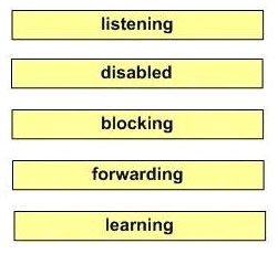
* At least one Layer 2 (access port or trunk) port exists, has a link “up” on this VLAN and is in spanning-tree forwarding state on the VLAN.

(Reference: http://www.cisco.com/en/US/docs/switches/lan/catalyst4500/12.2/37sg/configuration/guides/l3_int.html)

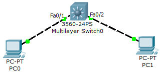
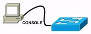
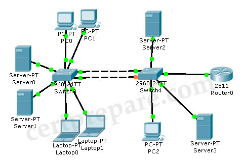
Let’s see an example of configuring Switch Virtual Interface (SVI) to perform interVLAN routing between PC0 & PC1:

SVI_simple_topology.jpg

Configuration

//Create two VLANs

L3Switch(config)#vlan 10
L3Switch(config-vlan)#vlan 20
L3Switch(config-vlan)#exit

L3Switch(config)#interface fa0/1
L3Switch(config-if)#switchport mode access
L3Switch(config-if)#switchport access vlan 10

L3Switch(config)#interface fa0/2
L3Switch(config-if)#switchport mode access
L3Switch(config-if)#switchport access vlan 20
L3Switch(config-if)#exit

//Enable IP routing on this Layer 3 Switch

L3Switch(config)#ip routing

//Create two SVIs for interVLAN routing:

L3Switch(config)#interface vlan 10
L3Switch(config-if)#ip address 10.0.0.1 255.255.255.0

L3Switch(config)#interface vlan 20
L3Switch(config-if)#ip address 20.0.0.1 255.255.255.0

On PC0, assign the IP address 10.0.0.2 255.255.255.0 and the default gateway: 10.0.0.1
On PC1, assign the IP address 20.0.0.2 255.255.255.0 and the default gateway: 20.0.0.1

Now we can ping from PC0 to PC1:

PC0>ping 20.0.0.2

Pinging 20.0.0.2 with 32 bytes of data:

Reply from 20.0.0.2: bytes=32 time=40ms TTL=127

VLAN VTP STP Questions

$
0
0

Here you will find answers to VLAN, VTP, STP questions

If you are not sure about VLAN, VTP, STP please read my VLAN tutorial, VTP tutorial and STP tutorial.

Question 1

Two switches SA and SB are connected as shown below. Given the below partial configuration, which two statements are true about VLAN traffic? (Choose two)

vtp_traffic

A – VLANs 1-5 will be blocked if fa0/10 goes down.
B – VLANs 6-10 have a port priority of 128 on fa0/10.
C – VLANs 6-10 will use fa0/10 as a backup only.
D – VLANs 1-10 are configured to load share between fa0/10 and fa0/12.


Answer: C D

Explanation:

Let’s assume that SA is the root bridge for all VLANs, it will make the explanation a bit clearer…

First we should understand what will happen if nothing is configured (use default values). Because we assumed that SA is the root bridge so all of its ports will forward. SB will need to block one of its ports to avoid a bridging loop between the two switches. But how does SB select its blocked port? Well, the answer is based on the BPDUs it receives from SA. A BPDU is superior than another if it has:

1. A lower Root Bridge ID
2. A lower path cost to the Root
3. A lower Sending Bridge ID
4. A lower Sending Port ID

These four parameters are examined in order. In this specific case, all the BPDUs sent by SA have the same Root Bridge ID, the same path cost to the Root and the same Sending Bridge ID. The only parameter left to select the best one is the Sending Port ID (Port ID = port priority + port index). If using default values, the default port priority’s value is 32 or 128 (128 is much more popular today but 32 is also a default port priority’s value), so SB will compare port index values, which are unique to each port on the switch, and because Fa0/12 is inferior to Fa0/10, SB will select the port connected with Fa0/10 (of SA) as its root port and block the other port.

vtp_traffic_explanation_blockFa012

To change the default decision of selecting root port, we can change the port priority of each interface. The above picture is true for VLAN 1-5 because port Fa0/10 has a lower port-priority so the peer port will be chosen as the root port. For VLAN 6-10, port Fa0/12 has higher priority ID (lower port priority value) so SB will block its upper port.

For answer A – “VLANs 1-5 will be blocked if fa0/10 goes down” – is not correct because if Fa0/10 goes down, SB will unblock its lower port therefore VLANs 1-5 will still operate.

For answer B – “VLANs 6-10 have a port priority of 128 on fa0/10″ – is not always correct because VLAN 6-10 can have a different port priority (of 32) according to the Cisco’s link below.

Answer C is correct because VLAN 6-10 uses Fa0/12 link as it main path. Fa0/10 is the backup path and is only opened when port Fa0/12 fails.

Answer D is correct because this configuration provide load-balance traffic based on VLAN basis. VLANs 1-5 use Fa0/10 and VLANs 6-10 use Fa0/12 as their main paths.

Note: We can not assure the answer B is always correct so we should choose C and D if the question asks us to give only 2 choices).

Reference (and good resource, too):

http://www.cisco.com/en/US/tech/tk389/tk621/technologies_tech_note09186a00800ae96a.shtml

Question 2:

The network operations center has received a call stating that Users in VLAN 107 are unable to access resources through R1. From the information contained in the graphic, what is the cause of this problem?

vtp_pruning

vtp_pruning_output.jpg

A – spanning tree is not enabled on VLAN 107
B – VTP is pruning VLAN 107
C – VLAN 107 does not exist on switch SA
D – VLAN 107 is not configured on the trunk


Answer: B

Explanation:

“VLAN allowed on trunk” – Each trunk allows all VLANs by default. However, administrator can remove or add to the list by using the “switchport trunk allowed” command.

“VLANs allowed and active in management” – To be active, a VLAN must be in this list.

“VLANs in spanning tree forwarding state and not pruned” – This list is a subset of the “allowed and active” list but with any VTP-pruned VLANs removed.

All VLANs were configured except VLAN 101 so D is not correct. VLAN 107 exists in the “allowed and active” section so A and C are not correct, too. In the “forwarding state and not pruned” we don’t see VLAN 107 so the administrator had wrongly configured this VLAN as pruned.

Question 3:

The network administrator needs to enable VTP pruning within the network. What action should a network administrator take to enable VTP pruning on an entire management domain?

A – enable VTP pruning on every switch in the domain
B – enable VTP pruning on any client switch in the domain
C – enable VTP pruning on any switch in the management domain
D – enable VTP pruning on a VTP server in the management domain


Answer: D

Question 4:

Study the diagram below carefully, which three statements are true? (Choose three)

dtp_diagram

dtp

A – DTP packets are sent from Switch SB.
B – DTP is not running on Switch SA.
C – A trunk link will be formed.
D – The native VLAN for Switch SB is VLAN 1.


Answer: A C D

Explanation:

Dynamic Trunking Protocol (DTP) is the Cisco-proprietary that actively attempts to negotiate a trunk link between two switches. If an interface is set to switchport mode dynamic desirable, it will actively attempt to convert the link into trunking mode. If the peer port is configured as switchport mode trunk, dynamic desirable, or dynamic auto mode, trunking is negotiated successfully -> C is correct.

SB is in “dynamic desirable” mode so it will send DTP packets to SA to negotiate a trunk link -> A is correct.

On an 802.1Q trunk, DTP packets are sent on the native VLAN. By default, it is VLAN 1 (notice that SA’s native VLAN is 5) -> D is correct.

(Note: an 802.1Q trunk’s native VLAN is the only VLAN that has untagged frames)

Below is the switchport modes for easy reference:

Mode Function
Dynamic Auto Creates the trunk based on the DTP request from the neighboring switch.
Dynamic Desirable Communicates to the neighboring switch via DTP that the interface would like
to become a trunk if the neighboring switch interface is able to become a trunk.
Trunk Automatically enables trunking regardless of the state of the neighboring switch
and regardless of any DTP requests sent from the neighboring switch.
Access Trunking is not allowed on this port regardless of the state of the neighboring
switch interface and regardless of any DTP requests sent from the neighboring
switch.
Nonegotiate Prevents the interface from generating DTP frames. This command can be
used only when the interface switchport mode is access or trunk. You must
manually configure the neighboring interface as a trunk interface to establish a
trunk link.


Question 5:

Regarding the exhibit and the partial configuration of switch SA and SB. STP is configured on all switches in the network. SB receives this error message on the console port:

00:06:34: %CDP-4-DUPLEX_MISMATCH: duplex mismatch discovered on FastEthernet0/5 (not half duplex), with SA FastEthernet0/4 (half duplex), with TBA05071417(Cat6K-B) 0/4 (half duplex).

What would be the possible outcome of the problem?

STP_mismatched_duplex.jpg

A – The root port on switch P4S-SB will fall back to full-duplex mode.
B – The interfaces between switches P4S-SA and P4S-SB will transition to a blocking state.
C – The root port on switch P4S-SA will automatically transition to full-duplex mode.
D – Interface Fa0/6 on switch SB will transit to a forwarding state and create a bridging loop.


Answer: D

Explanation:

From the output, we learned that the interfaces on two switches are operating in different duplex modes: Fa0/4 of SA in half-duplex mode & Fa0/5 of SB in full-duplex mode. In this case, because SB is operating in full duplex mode, it does not check the carrier sense before sending frames (CSMA/CD is not used in full-duplex mode). Therefore, SB can start to send frames even if SA is using the link and a collision will occur. The result of this is SA will wait a random time before attempting to transmit another frame. If B sends enough frames to A to make every frame sent from A (which includes the BPDUs) get dropped then SB can think it has lost root bridge (B does not receive BPDUs from A anymore). Therefore SB will unblock its Fa0/6 interface for transmitting and cause a bridging loop.

Drag and Drop Questions 3

$
0
0

Question 1

packet_cos_priority.jpg


Answer:

+ voice
+ video interactive
+ video streaming
+ call signaling
+ ip routing
+ network management

(http://www.cisco.com/en/US/docs/solutions/Enterprise/WAN_and_MAN/QoS_SRND/QoSIntro.html)

Question 2

Drag and drop the appropriate characteristics of Local VLANs and End-to-end VLANs

local_VLAN_end-to-end_VLAN.jpg


Answer:

Local VLANs:
+ easy to maintain
+ users are based on geographic boundaries or their physical location

End-to-end VLANs:
+ users are grouped into VLANs independent of a physical location
+ each VLAN has a common set of security and resource
+ users are assigned to the vlan regardless of their physical location within the campus n/w
+ Based on port security

Explanation

End-to-end VLAN: VLAN members reside on different switches throughout the network. They are used when hosts are assigned to VLANs for policy reasons, rather than physical location.

Local VLAN: Hosts are assigned to VLANs based on their location, such as a floor in a building. This design is more scalable and easier to troubleshoot because the traffic flow is more deterministic. It enables more redundancy and minimizes failure domains.

(Reference: CCNP SWITCH 642-813 Quick Reference Guide)

Question 3

Drag the steps on the left that should be part of a VLAN-based verification plan to the spaces on the right. Not all choices will be used.

VLAN_based_verification_plan.jpg


Answer:
+ Verify that there is inter-switch connectivity
+ Verify that switchports are properly pruned
+ Verify that creation of the virtual interface
+ Verify that the VLAN is assigned to the proper port

Question 4

Wireless LWAPP Association and Discovery Process Drag & Drop. Note not all options are used

LWAPP_Association_Discovery_Process.jpg


Answer:
+ The IP Address is statically configured on the Lightweight AP
+ The Lightweight AP requests an IP address via DHCP
+ The Lightweight AP searches for a wireless LAN controller using LWAPP in Layer 2 Mode
+ The Lightweight AP sends a LWAPP Discovery request to the management IP address of the Wireless LAN Controller via Broadcast
+ The Wireless LAN Controller responds with a Discovery Response from the Manager IP address
+ The Lightweight AP chooses the AP Manager with the least number of associated access points and sends the join request

Explanation

This sequence of events must occur in order for an LAP to register to a WLC:
1. The LAPs issue a DHCP discovery request to get an IP address, unless it has previously had a static IP address configured.
2. The LAP sends LWAPP discovery request messages to the WLCs.
3. Any WLC that receives the LWAPP discovery request responds with an LWAPP discovery response message.
4. From the LWAPP discovery responses that the LAP receives, the LAP selects a WLC to join.
5. The LAP then sends an LWAPP join request to the WLC and expects an LWAPP join response.
6. The WLC validates the LAP and then sends an LWAPP join response to the LAP.
7. The LAP validates the WLC, which completes the discovery and join process. The LWAPP join process includes mutual authentication and encryption key derivation, which is used to secure the join process and future LWAPP control messages.
8. The LAP registers with the controller.

You can watch a video explaining how the Lightweight Access Point Registration with Wireless LAN Controller (WLC) here https://supportforums.cisco.com/videos/2649.


Drag and Drop Questions 2

$
0
0

Here you will find answers to Drag and Drop Questions – Part 2

Question 1

Drag the choices on the left to the boxes on the right that should be included when creating a VLAN-based implementation plan. Not all choices will be used.

VLAN_implementation_plan.jpg


Answer:

+ reference to design documents
+ roll back guidelines
+ detailed implementation plans
+ time required to perform the implementation

(In this question we don’t need to sort in the correct order)

Explanation

An implementation plan requires:

+ A description of the task
+ References to design documents
+ Detailed implementation guidelines
+ Detailed rollback guidelines in case of failure
+ The estimated time required for implementation

Question 2

You have a VLAN implementation that requires inter-vlan routing using layer 3 switches. Drag the steps on the left that should be part of the verification plan to the spaces on the right. Not all choices will be used.

VLAN_implementation.jpg


Answer:

+ Verify that there is inter-switch connectivity
+ Verify that the data and voice VLANs are NOT assigned a trunk’s native VLAN
+ Verify that the needed Switch Virtual interfaces have been created
+ Verify that the proper ports are assigned to the VLAN

Question 3

Match the SNMP versions and associated features

SNMP_version_features.jpg


Answer:

v1:
+ get next request
+ unsolicited alert msg

v2:
+ informed request
+ incremental 64 bit of new data

v4:
+ user name
+ security level

Question 4

Categorize the high availability network resource or feature with the management level, network level, or system level used.

network_resources.jpg


Answer:

Management Level:
+ IP SLA responder
+ NTP

Network Level:
+ RSTP
+ NSF

System Level:
+ Dual Power Supplies
+ SSO

Question 5

Match the HSRP states on the left with the correct definition on the right.

HSRP states.jpg


Answer:

+ Initial: State from which the router begin the HSRP process
+ Standby: A candidate to become the next active router
+ Learn: The router is still waiting to hear from the active router
+ Active: The router is currently forwarding packets
+ Listen: Listens for hello messages from the active and standby router
+ Speak: Participates in the election for the active or standby router

Question 6

Sort the syslog priority from highest to lowest

syslog_priority.jpg


Answer:

1) emergency
2) alert
3) critical
4) error
5) warning
6) notice
7) informational
8) debug

Explanation

The syslog levels and descriptions are listed below:

Code Severity Description
0 Emergency system is unusable (such as an imminent system crash)
1 Alert action must be taken immediately (such as a corrupted system database)
2 Critical Critical conditions (such as a hardware error)
3 Error Error conditions
4 Warning Warning conditions
5 Notice normal but significant condition. It is not an error, but possibly should be handled in a special way
6 Informational Informational message
7 Debug Debug-level message

Question 7

Match the Attributes on the left with the types of VLAN designs on right.

VLAN_attributes.jpg


Answer:

End-to-End VLANs:
+ As a user moves through a campus, the VLAN membership of the user remains the same, regardless of the physical switch this user attaches to.
+ Users are grouped into each VLAN regardless of the physical locations.

Local VLANs:
+ Create with Physical boundaries in mind rather then the departments or organization of the users on the devices.
+ VLANs on one switch are not advertised to all other switches in the network, nor do they need to be created in the VLAN database of any other switch.

Question 8

You have been tasked with planning a VLAN solution that will connect a seiver in one buliding to several hosts in another building. The solution should be built using the local vlan model and layer 3 switching at the distribution layer. Identify the questions related to this vlan solution that would ask the network administrator before you start the planning by dragging them into the target zone one the right. Not all questions will be used.

VLAN_soutions.jpg


Answer:

+ Is there inter-switch connectivity?
+ What routing protocol will be used?
+ What VLANs are available on each switch?
+ What switch ports are available in each building?
+ What IP addresses are available on each subnet?

Question 9

local_VLAN_distributed_VLAN.jpg


Answer:

Local vlan:
+ 20/80 rule
+ leverages on stp
+ leverages on routing
+ locally significant

Distributed vlan:
+ 80/20 rule
+ leverages on vtp
+ leverages on switching
+ globally significant

Drag and Drop Questions

$
0
0

Here you will find answers to Drap and Drop questions

Question 1:

Place the DTP mode with its correct description:

DTP_modes


Answer:

1) Trunk: Set the switch port to trunk mode and negotiate to become a trunk.
2) Nonegotiate: Specify that the DTP packets are not sent out of this interface.
3) Access: Set a switch port to permanent nontrunking mode.
4) Dynamic Auto: Set the switch port to respond, but not actively send DTP frames.
5) Dynamic Desirable: Make the interface actively attempt to convert the link to a trunk link. (This means the interface is ready to autonegotiate trunking encapsulation and form a trunk link (using DTP) with a neighbor port in desirable, auto, or on mode.)

Explanation:

Dynamic Trunking Protocol (DTP) is the Cisco-proprietary that actively attempts to negotiate a trunk link between two switches. Below is the switchport modes (or DTP modes) for easy reference:

Mode Function
Dynamic Auto Creates the trunk based on the DTP request from the neighboring switch.
Dynamic Desirable Communicates to the neighboring switch via DTP that the interface would like
to become a trunk if the neighboring switch interface is able to become a trunk.
Trunk Automatically enables trunking regardless of the state of the neighboring switch
and regardless of any DTP requests sent from the neighboring switch.
Access Trunking is not allowed on this port regardless of the state of the neighboring
switch interface and regardless of any DTP requests sent from the neighboring
switch.
Nonegotiate Prevents the interface from generating DTP frames. This command can be
used only when the interface switchport mode is access or trunk. You must
manually configure the neighboring interface as a trunk interface to establish a
trunk link.

Question 2:

This is a drag and drop question which is about the correct sequence of steps that a wireless client takes during the process of association with an access point (AP). Drag the items to the proper locations.

wireless_association.jpg


Answer:

wireless_association_answer.jpg

Explanation:

Any wireless client attempting to use the wireless network must first arrange a membership with the AP. Membership with the AP is called an association. The client must send an association request message, and the AP grants or denies the request by sending an association reply message. Once associated, all communications to and from the client must pass through the AP. Clients associate with access points as follows:

1) The client sends a probe request.
2) The AP sends a probe response.
3) The client initiates an association to an AP. Authentication and any other security information is sent to the AP.
4) The AP accepts the association.
5) The AP adds the client’s MAC address to its association table.


Question 3:

Drag and drop question. Drag the items to the proper locations.

STP_process


Answer:

STP_process_answer

1) Listening: sends and receives BPDUs to determine root, but does not update the MAC address table.
2) Disabled: does not participate in frame forwarding or in STP.
3) Blocking: does not participate in frame forwarding.
4) Fowarding: sends and receives data frames.
5) Learning: populates the MAC address table, but will not forward user data.

Notice: A port begins its life in a Disabled state, moving through several passive states and, finally, into an active state if allowed to forward traffic.

Question 4 (not sure about the question)

network level – RSTP, NSF
system level – Dual power supply, SSO
management level – NTP , IP SLA

verify that the vlan is assigned to the proper ports
verify that creation of the virtual interface
Verify that there is inter-switch connectivity
verify that switchports are properly pruned

Number of IP Subnets
VLAN to IP mapping
Location of each VLAN
VLAN assignments


HSRP Hotspot

$
0
0

Question:

HSRP_Hotspot

- DSW1( Distribute switch 1) is the primary device for Vlan 101, 102, 105
– DSW2 ( Distribute switch 2) is the primary device for Vlan 103 and 104


Question 1:


During routine maintenance, it became necessary to shutdown G1/0/1 on DSW1. All other interface were up. During this time, DSW1 remained the active device for Vlan 102′s HSRP group. You have determined that there is an issue with the decrement value in the track command in Vlan 102′s HSRP group. What need to be done to make the group function properly?

A. The DSW1′s decrement value should be configured with a value from 5 to 15
B. The DSW1′s decrement value should be configured with a value from 9 to 15
C. The DSW1′s decrement value should be configured with a value from 11 to 18
D. The DSW1′s decrement value should be configured with a value from 195 to less than 205
E. The DSW1′s decrement value should be configured with a value from 200 to less than 205
F. The DSW1′s decrement value should be greater than 190 and less 200


Answer: C

Explanation:

The question clearly stated that there was an issue with the decrement value in VLAN 102 so we should check VLAN 102 on both DSW1 and DSW2 switches first. Click on the PC Console1 and PC Console2 to access these switches then use the “show running-config” command on both switches

DSW1>enable
DSW1#show running-config

DSW2>enable
DSW2#show running-config

HSRP_show_run

As shown in the outputs, the DSW1′s priority is 200 and is higher than that of DSW2 so DSW1 becomes active switch for the group. Notice that the interface Gig1/0/1 on DSW1 is being tracked so when this interface goes down, HSRP automatically reduces the router’s priority by a configurable amount, in this case 5. Therefore the priority of DSW1 goes down from 200 to 195. But this value is still higher than that of DSW2 (190) so DSW1 remains the active switch for the group. To make DSW2 takes over this role, we have to configure DSW1′s decrement value with a value equal or greater than 11 so that its result is smaller than that of DSW2 (200 – 11 < 190). Therefore C is the correct answer.

Question 2:

During routine maintenance, G1/0/1 on DSW1 was shutdown. All other interface were up. DSW2 became the active HSRP device for Vlan101 as desired. However, after G1/0/1 on DSW1 was reactivated. DSW1 did not become the active HSRP device as desired. What need to be done to make the group for Vlan101 function properly?

A. Enable preempt on DSW1′s Vlan101 HSRP group
B. Disable preempt on DSW1′s Vlan101 HSRP group
C. Decrease DSW1′s priority value for Vlan101 HSRP group to a value that is less than priority value configured on DSW2′s HSRP group for Vlan101
D. Decrease the decrement in the track command for DSW1′s Vlan 101 HSRP group to a value less than the value in the track command for DSW2′s Vlan 101 HSRP group.


Answer: A

Explanation:

Continue to check VLAN 101 on both switches…

HSRP_show_run_2.jpg

We learned that DSW1 doesn’t have the “standby 1 preempt” command so it can’t take over the active role again even if its priority is the highest. So we need to enable this command on VLAN 101 of DSW1.

Question 3:

DSW2 has not become the active device for Vlan103′s HSRP group even though all interfaces are active. As related to Vlan103′s HSRP group. What can be done to make the group function properly?

A. On DSW1, disable preempt
B. On DSW1, decrease the priority value to a value less than 190 and greater than 150
C. On DSW2, increase the priority value to a value greater 241 and less than 249
D. On DSW2, increase the decrement value in the track command to a value greater than 10 and less than 50.


Answer: B or C

Explanation:

HSRP_vlan103

The reason DSW2 has not become the active switch for Vlan103 is because the priority value of DSW1 is higher than that of DSW2. In order to make DSW2 become the active switch, we need to increase DSW2′s priority (to higher than 200) or decrease DSW1′s priority (to lower than 190).

Question 4:

If G1/0/1 on DSW1 is shutdown, what will be the current priority value of the Vlan105′s group on DSW1?

A. 95
B. 100
C. 150
D. 200


Answer: A

Explanation:

Below is the output of VLAN 105:

HSRP_vlan105.jpg

If G1/0/1 on DSW1 is shutdown, its priority will decrease 55 so, its value will be 150 – 55 = 95

Question 5:

What is the configured priority value of the Vlan105′s group on DSW2 ?

A. 50
B. 100
C. 150
D. 200


Answer: B

Explanation:

Below is the output of VLAN 105 of DSW2:

HSRP_vlan105_DSW2.jpg

We don’t see the priority of DSW2 so it is using the default value (100).

Question 6:

During routine maintenance, it became necessary to shutdown G1/0/1 on DSW1 and DSW2. All other interface were up. During this time, DSW1 became the active device for Vlan104′s HSRP group. As related to Vlan104′s HSRP group, what can be done to make the group function properly?

A. On DSW1, disable preempt
B. On DSW2, decrease the priority value to a value less than 150
C. On DSW1, increase the decrement value in the track command to a value greater than 6
D. On DSW1, disable track command.


Answer: C

Explanation:

HSRP_vlan104

The question asks us how to keep the active role of DSW2. From the outputs, we learned that if both interfaces G1/0/1 of DSW1 and DSW2 are shutdown, the priority of DSW1 will be 150 – 1 = 149 and that of DSW2 will be 200 – 55 = 145 -> DSW1 will become the active switch.

The main point here is that we have to configure so in such a way that when both interfaces G1/0/1 of DSW1 and DSW2 are shutdown, the priority of DSW2 is still greater than that of DSW1. Therefore the priority value of DSW1 should be smaller than 145, or we have to configure the decrement value of DSW1 to a value greater than 6 ( 6 = 150 – 144) -> C is the correct answer.

Notice: To keep the active role of DSW2, we can disable “preempt” on DSW1 (answer A) so that it will not take over the active role when DSW1 is downed but it also means that VLAN 104 will not have active switch -> VLAN104 will fail.

STP Hotspot

$
0
0

Question

Online Incorporated is an internet game provide. The game service network had recently added an additional switch block with multiple VLANs configured. Unfortunately, system administrators neglected to document the spanning-tree topology during configuration. For baseline purpose, you will be required to identify the spanning-tree topology for the switch block. Using the output of “show spanning-tree” command on switch SW-C and the provided physical topology, answer the following questions:

SpanningTreeBCMSNHotspot

The output of “show spanning-tree” command on SW-C:

SpanningTree_show_spanning_tree


Question 1:

Which spanning Tree Protocol has been implemented on SW-B?

A. STP/IEEE 802.1D
B. MSTP/IEEE 802.1s
C. PVST+
D. PVRST
E. None of the above


Answer: C

Explanation:

On the Fa0/2 interface we can see the type of connection is P2p Peer (STP) and Cisco says that: “!— Type P2p Peer(STP) represents that the neighbor switch runs PVST.” Please visit this link to understand more http://www.cisco.com/en/US/products/hw/switches/ps708/products_configuration_example09186a00807b0670.shtml

Question 2:

Which bridge ID belongs to SW-B?

A. 24623.000f.34f5.0138
B. 32768.000d.bd03.0380
C. 32768.000d.65db.0102
D. 32769.000d.65db.0102
E. 32874.000d.db03.0380
F. 32815.000d.db03.0380


Answer: A

Explanation:

Have a look at the output at VLAN0047:

SpanningTree_show_spanning_tree_VLAN47

Notice there are two “Cost” value in the picture, the above “Cost” is the total cost from the current switch to the root bridge while the second “Cost” refers to the cost on that interface (Fa0/2). Both these “Cost” are the same so we can deduce that the root bridge is connectly directly to this switch on Fa0/2 interface -> the root bridge is Switch B, and the “Address” field shows its MAC address 000f.34f5.0138. Notice Bridge ID = Bridge Priority + MAC address.

Question 3:

Which port role has interface Fa0/2 of SW-A adopted for VLAN 47?

A. Root port
B. Nondesigned port
C. Designated port
D. Backup port
E. Alternate port


Answer: C

Explanation:

We learned that Switch B is the root bridge for VLAN 47 so port Fa0/1 on SwitchA and Fa0/2 on SwitchC should be the root ports, and from the output of SwitchC, we knew that port Fa0/1 of SwitchC is in blocking state. Therefore its opposite port on SwitchA must be in designated state (forwarding).

So, can Fa0/2 of SW-A be in blocking state? The answer is no so that BPDU packets can be received on Fa0/1 of SW-C. It will remain in blocking state as long as a steady flow of BPDUs is received.


Question 4:

Which port state is interface Fa0/2 of SW-B in for VLANs 1 and 106?

A. Listening
B. Learning
C. Disabled
D. Blocking
E. Forwarding
F. Discarding


Answer: D

Explanation:

As explained in question 2, we can deduce SW-A is the root bridge for VLANs 1 and 106 so ports Fa0/1 on SW-B and SW-C will be the root ports. From the output of SW-C for VLANs 1 and 106, port Fa0/2 of this switch is designated (forwarding) so we can deduce interface Fa0/2 of SW-B is in blocking status.

Question 5:

Which bridge ID belongs to SW-A?

A. 24623.000f.34f5.0138
B. 32768.000d.bd03.0380
C. 32768.000d.65db.0102
D. 32769.000d.65db.0102
E. 32874.000d.db03.0380
F. 32815.000d.db03.0380


Answer: D

Explanation:

SW-A is the root bridge for VLANs 1 and 106 and we can easily find the MAC address of this root bridge from the output of SW-C, it is 000d.65db.0102. Notice that SW-A has 2 bridge IDs for VLANs 1 and 106, they are 32769.000d.65db.0102 and 24682.000d.65db.0102


AAAdot1x Lab Sim

$
0
0

Question:

Acme is a small shipping company that has an existing enterprise network comprised of 2 switches;DSW1 and ASW1. The topology diagram indicates their layer 2 mapping. VLAN 40 is a new VLAN that will be used to provide the shipping personnel access to the server. For security reasons, it is necessary to restrict access to VLAN 20 in the following manner:
– Users connecting to ASW1’s port must be authenticate before they are given access to the network. Authentication is to be done via a Radius server:
– Radius server host: 172.120.39.46
– Radius key: rad123
– Authentication should be implemented as close to the host device possible.
– Devices on VLAN 20 are restricted to in the address range of 172.120.40.0/24.
– Packets from devices in the address range of 172.120.40.0/24 should be passed on VLAN 20.
– Packets from devices in any other address range should be dropped on VLAN 20.
– Filtering should be implemented as close to the server farm as possible.
The Radius server and application servers will be installed at a future date. You have been tasked with implementing the above access control as a pre-condition to installing the servers. You must use the available IOS switch features.

AAAdot1x.jpg


Answer and Explanation:


1) Configure ASW1

Enable AAA on the switch:
ASW1(config)#
aaa new-model

The new-model keyword refers to the use of method lists, by which authentication methods and sources can be grouped or organized.

Define the server along with its secret shared password:
ASW1(config)#radius-server host 172.120.39.46 key rad123

ASW1(config)#aaa authentication dot1x default group radius
This command causes the RADIUS server defined on the switch to be used for 802.1x authentication.

Enable 802.1x on the switch:
ASW1(config)#dot1x system-auth-control

Configure Fa0/1 to use 802.1x:

ASW1(config)#interface fastEthernet 0/1
ASW1(config-if)#switchport mode access
ASW1(config-if)#dot1x port-control auto
Notice that the word “auto” will force connected PC to authenticate through the 802.1x exchange.

ASW1(config-if)#exit
ASW1#copy running-config startup-config

2) Configure DSW1:

Define an access-list:
DSW1(config)#ip access-list standard 10 (syntax: ip access-list {standard | extended} acl-name)
DSW1(config-std-nacl)#permit 172.120.40.0 0.0.0.255
DSW1(config-std-nacl)#exit

Define an access-map which uses the access-list above:
DSW1(config)#vlan access-map MYACCMAP 10 (syntax: vlan access-map map_name [0-65535] )
DSW1(config-access-map)#match ip address 10 (syntax: match ip address {acl_number | acl_name})
DSW1(config-access-map)#action forward
DSW1(config-access-map)#exit

DSW1(config)#vlan access-map MYACCMAP 20
DSW1(config-access-map)#action drop (drop other networks)
DSW1(config-access-map)#exit

Apply a vlan-map into a vlan:
DSW1(config)#vlan filter MYACCMAP vlan-list 20 (syntax: vlan filter mapname vlan-list list)

DSW1#copy running-config startup-config

(Notice: Many reports said the copy running-config startup-config didn’t work but they still got the full mark)


Other lab-sims in this site:

LACP with STP Sim
MLS and EIGRP Sim
VTP Lab 2
VTP Lab
Spanning Tree Lab Sim


Spanning Tree Lab Sim

$
0
0

Question:

The headquarter office for a cement manufacturer is installing a temporary Catalyst 3550 in an IDF to connect 24 additional users. To prevent network corruption, it is important to have the correct configuration prior to connecting to the production network. It will be necessary to ensure that the switch does not participate in VTP but forwards VTP advertisements that are received on trunk ports.
Because of errors that have been experienced on office computers, all nontrunking interfaces should transition immediately to the forwarding state of Spanning tree. Also, configure the user ports (all FastEthernet ports) so that the ports are permanently nontrunking.

SpanningTreeLab.jpg

Requirements:
You will configure FastEthernet ports 0/12 through 0/24 for users who belong to VLAN 20. Also, all VLAN and VTP configurations are to be completed in global configuration mode as VLAN database mode is being deprecated by Cisco. You are required to accomplish the following tasks:

1. Ensure the switch does not participate in VTP but forwards VTP advertisements received on trunk ports.
2. Ensure all non-trunking interfaces (Fa0/1 to Fa0/24) transition immediately to the forwarding state of Spanning-Tree.
3. Ensure all FastEthernet interfaces are in a permanent non-trunking mode.
4. Place FastEthernet interfaces 0/12 through 0/24 in VLAN 20.

Answer and Explanation:

Switch>enable
Switch#configure terminal
Switch(config)#interface range fa0/1 – 24
Switch(config-if-range)#switchport mode access (Make all FasEthernet interfaces into access mode)
Switch(config-if-range)#spanning-tree portfast (Enables the PortFast on interface)

Next, we need to assign FastEthernet ports 0/12 through 0/24 to VLAN 20.

By default, all ports on the switch are in VLAN 1. To change the VLAN associated with a port, you need to go to each interface (or a range of interfaces) and tell it which VLAN to be a part of.

Switch(config-if-range)#interface range fa0/12 – 24
Switch(config-if-range)#switchport access vlan 20 (Make these ports members of vlan 20)
Switch(config-if-range)#exit

Next we need to make this switch in transparent mode. In this mode, switch doesn’t participate in the VTP domain, but it still forwards VTP advertisements through any configured trunk links.

Switch(config)#vtp mode transparent
Switch(config)#exit
Switch#copy running-config startup-config

(Notice: Many reports said the copy running-config startup-config didn’t work but they still got the full mark)


Other lab-sims in this site:

LACP with STP Sim
MLS and EIGRP Sim
VTP Lab 2
VTP Lab
AAAdot1x Lab Sim

VTP Lab

$
0
0

Question:

The headquarter offices for a book retailer are enhancing their wiring closets with Layer3 switches. The new distribution-layer switch has been installed and a new access-layer switch cabled to it. Your task is to configure VTP to share VLAN information from the distribution-layer switch to the access-layer devices. Then, it is necessary to configure interVLAN routing on the distribution layer switch to route traffic between the different VLANs that are configured on the access-layer switches; however, it is not necessary for you to make the specific VLAN port assignments on the access-layer switches. Also, because VLAN database mode is being deprecated by Cisco, all VLAN and VTP configurations are to be completed in the global configuration mode. Please reference the following table for the VTP and VLAN information to be configured:

VTP_Lab.jpg

Requirements:

VTP Domain name cisco  
VLAN Ids 20 21
IP Addresses 172.16.71.1/24 172.16.132.1/24

These are your specific tasks:

1. Configure the VTP information with the distribution layer switch as the VTP server
2. Configure the VTP information with the access layer switch as a VTP client
3. Configure VLANs on the distribution layer switch
4. Configure inter-VLAN routing on the distribution layer switch
5. Specific VLAN port assignments will be made as users are added to the access layer switches in the future.
6. All VLANs and VTP configurations are to completed in the global configuration. To configure the switch click on the host icon that is connected to the switch be way of a serial console cable.

Answer and Explanation:


1) Configure the VTP information with the distribution layer switch as the VTP server:


DLSwitch#configure terminal
DLSwitch(config)#vtp mode server
DLSwitch(config)#vtp domain cisco (use cisco, not CISCO because it is case sensitive)

(Requirement 2 will be solved later)
3) Configure VLANs on the distribution layer switch

To create VLANs on a switch, use the vlan vlanID# command:
DLSwitch(config)#vlan 20
DLSwitch(config)#vlan 21

Configure Ip addresses for Vlans:

DLSwitch(config)#interface vlan 20
DLSwitch(if-config)#ip address 172.16.71.1 255.255.255.0
DLSwitch(if-config)#no shutdown
DLSwitch(if-config)#interface vlan 21
DLSwitch(if-config)#ip address 172.16.132.1 255.255.255.0
DLSwitch(if-config)#no shutdown
DLSwitch(if-config)#exit

4) Configure inter-VLAN routing on the distribution layer switch

DLSwitch(config)#ip routing
DLSwitch(config)#exit
DLSwitch#copy running-config startup-config

2) Configure the VTP information with the access layer switch as a VTP client

ALSwitch#configure terminal
ALSwitch(config)#vtp mode client
ALSwitch(config)#vtp domain cisco
ALSwitch(config)#exit

ALSwitch#copy running-config startup-config

(Notice: Many reports said the copy running-config startup-config didn’t work but they still got the full mark)

Other lab-sims in this site:

LACP with STP Sim
MLS and EIGRP Sim
VTP Lab 2
Spanning Tree Lab Sim
AAAdot1x Lab Sim


VTP Lab 2

$
0
0

Question:

Acme is a small export company that has an existing enterprise network comprised of 5 switches;
CORE,DSW1,DSW2,ASW1 and ASW2. The topology diagram indicates their desired pre-VLAN spanning tree mapping.
Previous configuration attempts have resulted in the following issues:
– CORE should be the root bridge for VLAN 20; however, DSW1 is currently the root bridge for VLAN 20.
– Traffic for VLAN 30 should be forwarding over the gig 1/0/6 trunk port between DSW1 and DSW2. However VLAN 30 is currently using gig 1/0/5.
– Traffic for VLAN 40 should be forwarding over the gig 1/0/5 trunk port between DSW1 and DSW2. However VLAN 40 is currently using gig 1/0/6.

You have been tasked with isolating the cause of these issuer and implementing the appropriate solutions. You task is complicated by the fact that you only have full access to DSW1, with isolating the cause of these issues and implementing the appropriate solutions. Your task is complicated by the fact that you only have full access to DSW1, with the enable secret password cisco. Only limited show command access is provided on CORE, and DSW2 using the enable 2 level with a password of acme. No configuration changes will be possible on these routers. No access is provided to ASW1 or ASW2.


VTP_Troubleshooting

Answer and Explanation:

1) “CORE should be the root bridge for VLAN 20; however, DSW1 is currently the root bridge for VLAN 20″ -> We need to make CORE switch the root bridge for VLAN 20.

By using the “show spanning-tree” command as shown above, we learned that DSW1 is the root bridge for VLAN 20 (notice the line “This bridge is the root”).

DSW1>enable
DSW1#show spanning-tree

VTP_Lab2_show_spanning-tree

To determine the root bridge, switches send and compare their priorities and MAC addresses with each other. The switch with the lowest priority value will have highest priority and become the root bridge. Therefore, we can deduce that the priority of DSW1 switch is lower than the priority of the CORE switch so it becomes the root bridge. To make the CORE the root bridge we need to increase the DSW1′s priority value, the best value should be 61440 because it is the biggest value allowed to assign and it will surely greater than of CORE switch. (You can use another value but make sure it is greater than the CORE priority value by checking if the CORE becomes the root bridge or not; and that value must be in increments of 4096).

(Notice that the terms bridge and switch are used interchangeably when discussing STP)

DSW1#configure terminal
DSW1(config)#spanning-tree vlan 20 priority 61440

2) “Traffic for VLAN 30 should be forwarding over the gig 1/0/6 trunk port between DSW1 and DSW2. However VLAN 30 is currently using gig 1/0/5″

DSW1 is the root bridge for VLAN 30 (you can re-check with the show spanning-tree command as above), so all the ports are in forwarding state for VLAN 30. But the question said that VLAN 30 is currently using Gig1/0/5 so we can guess that port Gig1/0/6 on DSW2 is in blocking state (for VLAN 30 only), therefore all traffic for VLAN 30 will go through port Gig1/0/5.

VTP_Lab2_VLAN30_Blocking

The root bridge for VLAN 30, DSW1, originates the Bridge Protocol Data Units (BPDUs) and switch DSW2 receives these BPDUS on both Gig1/0/5 and Gig1/0/6 ports. It compares the two BPDUs received, both have the same bridge-id so it checks the port cost, which depends on the bandwidth of the link. In this case both have the same bandwidth so it continues to check the sender’s port id (includes port priority and the port number of the sending interface). The lower port-id value will be preferred so the interface which received this port-id will be the root and the other interface (higher port-id value) will be blocked.

In this case port Gig1/0/6 of DSW2 received a Priority Number of 128.6 (means that port priority is 128 and port number is 6) and it is greater than the value received on port Gig1/0/5 (with a Priority Number of 128.5) so port Gig1/0/6 will be blocked. You can check again with the “show spanning-tree” command. Below is the output (notice this command is issued on DSW1 – this is the value DSW2 received and used to compare).

VTP_Lab2_show_spanning-tree_VLAN30

Therefore, all we need to do is to change the priority of port Gig1/0/6 to a lower value so the neighboring port will be in forwarding state. Notice that we only need to change this value for VLAN 30, not for all VLANs.

DSW1(config)#interface g1/0/6
DSW1(config-if)#spanning-tree vlan 30 port-priority 64
DSW1(config-if)#exit

3) “Traffic for VLAN 40 should be forwarding over the gig 1/0/5 trunk port between DSW1 and DSW2. However VLAN 40 is currently using gig 1/0/6″

Next we need to make sure traffic for VLAN 40 should be forwarding over Gig1/0/5 ports. It is a similar job, right? But wait, we are not allowed to make any configurations on DSW2, how can we change its port-priority for VLAN 40? There is another solution for this…

Besides port-priority parameter, there is another value we can change: the Cost value (or Root Path Cost). Although it depends on the bandwidth of the link but a network administrator can change the cost of a spanning tree, if necessary, by altering the configuration parameter in such a way as to affect the choice of the root of the spanning tree.

Notice that the Root Path Cost is the cost calculated by adding the cost in the received hello to the cost of the interface the hello BPDU was received. Therefore if you change the cost on an interface of DSW1 then only DSW1 will learn the change.

By default, the cost of a 100Mbps link is 19 but we can change this value to make sure that VLAN 40 will use interface Gig1/0/5.

DSW1(config)#interface g1/0/5
DSW1(config-if)#spanning-tree vlan 40 cost 1

DSW1(config-if)#end

You should re-check to see if everything was configured correctly:

DSW1#show spanning-tree

Save the configuration:

DSW1#copy running-config startup-config

(Notice: Many reports said the copy running-config startup-config didn’t work but they still got the full mark)

Remember these facts about Spanning-tree:

Path Selection:

1) Prefer the neighbor advertising the lowest root ID
2) Prefer the neighbor advertising the lowest cost to root
3) Prefer the neighbor with the lowest bridge ID
4) Prefer the lowest sender port ID

Spanning-tree cost:

spanningtree_cost

Other good resource for reference:

http://www.cisco.com/en/US/tech/tk389/tk621/technologies_tech_note09186a00800ae96a.shtml


Other lab-sims in this site:

LACP with STP Sim
MLS and EIGRP Sim
VTP Lab
Spanning Tree Lab Sim
AAAdot1x Lab Sim


MLS and EIGRP Sim

$
0
0

Question

You have been tasked with configuring multilayer SwitchC, which has a partial configuration and has been attached to RouterC as shown in the topology diagram.

You need to configure SwitchC so that Hosts H1 and H2 can successful ping the server S1. Also SwitchC needs to be able to ping server S1. Due to administrative restrictions and requirements you should not add/delete VLANs, changes VLAN port assignments or create trunk links. Company policies forbid the use of static or default routing. All routes must be learned via EIGRP 650 routing protocol.

You do not have access to RouterC, RouterC is correctly configured. No trunking has been configured on RouterC.
Routed interfaces should use the lowest host on a subnet when possible. The following subnets are available to implement this solution:
– 10.10.10.0/24
– 190.200.250.32/27
– 190.200.250.64/27
Hosts H1 and H2 are configured with the correct IP address and default gateway.
SwitchC uses Cisco as the enable password.
Routing must only be enabled for the specific subnets shown in the diagram.

EIGRP_MLS_sim.jpg

Answer and Explanation

In real life, there are two ways to configure interVLAN routing in this case:

+ Use RouterC as a “router on a stick” and SwitchC as a pure Layer2 switch. Trunking must be established between RouterC and SwitchC.
+ Only use SwitchC for interVLAN routing without using RouterC, SwitchC should be configured as a Layer 3 switch (which supports ip routing function as a router). No trunking requires.

The question clearly states “No trunking has been configured on RouterC” so RouterC does not contribute to interVLAN routing of hosts H1 & H2 -> SwitchC must be configured as a Layer 3 switch with SVIs for interVLAN routing.

We should check the default gateways on H1 & H2. Click on H1 and H2 and type the “ipconfig” command to get their default gateways.

C:\>ipconfig

We will get the default gateways as follows:

Host1:
+ Default gateway: 190.200.250.33

Host2:
+ Default gateway: 190.200.250.65

Now we have enough information to configure SwitchC (notice the EIGRP AS in this case is 650)

Note: VLAN2 and VLAN3 were created and gi0/10, gi0/11 interfaces were configured as access ports so we don’t need to configure them in this sim.

SwitchC# configure terminal
SwitchC(config)# int gi0/1
SwitchC(config-if)#no switchport -> without using this command, the simulator does not let you assign IP address on Gi0/1 interface.
SwitchC(config-if)# ip address 10.10.10.2 255.255.255.0 ->RouterC has used IP 10.10.10.1 so this is the lowest usable IP address.
SwitchC(config-if)# no shutdown
SwitchC(config-if)# exit
SwitchC(config)# int vlan 2
SwitchC(config-if)# ip address 190.200.250.33 255.255.255.224
SwitchC(config-if)# no shutdown
SwitchC(config-if)# int vlan 3
SwitchC(config-if)# ip address 190.200.250.65 255.255.255.224
SwitchC(config-if)# no shutdown
SwitchC(config-if)#exit
SwitchC(config)# ip routing (Notice: MLS will not work without this command)
SwitchC(config)# router eigrp 650
SwitchC(config-router)# network 10.10.10.0 0.0.0.255
SwitchC(config-router)# network 190.200.250.32 0.0.0.31
SwitchC(config-router)# network 190.200.250.64 0.0.0.31

NOTE : THE ROUTER IS CORRECTLY CONFIGURED, so you will not miss within it in the exam , also don’t modify/delete any port just do the above configuration. Also some reports said the “no auto-summary” command can’t be used in the simulator, in fact it is not necessary because the network 190.200.0.0/16 is not used anywhere else in this topology.

In order to complete the lab , you should expect the ping to SERVER to succeed from the MLS , and from the PCs as well.

Also make sure you use the correct EIGRP AS number (in the configuration above it is 650 but it will change when you take the exam) but we are not allowed to access RouterC so the only way to find out the EIGRP AS is to look at the exhibit above. If you use wrong AS number, no neighbor relationship is formed between RouterC and SwitchC.

In fact, we are pretty sure instead of using two commands “network 190.200.250.32 0.0.0.31″ and “network 190.200.250.64 0.0.0.31″ we can use one simple command “network 190.200.0.0″ because it is the nature of distance vector routing protocol like EIGRP: only major networks need to be advertised; even without “no auto-summary” command the network still works correctly. But in the exam the sim is just a flash based simulator so we should use two above commands, just for sure. But after finishing the configuration, we can use “show run” command to verify, only the summarized network 190.200.0.0 is shown.

Other lab-sims in this site:

LACP with STP Sim
VTP Lab 2
VTP Lab
Spanning Tree Lab Sim
AAAdot1x Lab Sim

LACP with STP Sim

$
0
0

Question

You work for SWITCH.com. They have just added a new switch (SwitchB) to the existing network as shown in the topology diagram.

LACP_STP_topology.jpg

RouterA is currently configured correctly and is providing the routing function for devices on SwitchA and SwitchB. SwitchA is currently configured correctly, but will need to be modified to support the addition of SwitchB. SwitchB has a minimal configuration. You have been tasked with competing the needed configuring of SwitchA and SwitchB. SwitchA and SwitchB use Cisco as the enable password.

Configuration Requirements for SwitchA

- The VTP and STP configuration modes on SwitchA should not be modified.
– SwitchA needs to be the root switch for vlans 11, 12, 13, 21, 22 and 23. All other vlans should be left are their default values.

Configuration Requirements for SwitchB

- Vlan 21, Name: Marketing, will support two servers attached to fa0/9 and fa0/10
– Vlan 22, Name: Sales, will support two servers attached to fa0/13 and fa0/14
– Vlan 23, Name: Engineering, will support two servers attached to fa0/15 and fa0/16
– Access ports that connect to server should transition immediately to forwarding state upon detecting the connection of a device.
– SwitchB VTP mode needs to be the same as SwitchA.
– SwitchB must operate in the same spanning tree mode as SwitchA.
– No routing is to be configured on SwitchB.
– Only the SVI vlan 1 is to be configured and it is to use address 192.168.1.11/24.

Inter-switch Connectivity Configuration Requirements:

- For operational and security reasons trunking should be unconditional and Vlans 1, 21, 22 and 23 should tagged when traversing the trunk link.
– The two trunks between SwitchA and SwitchB need to be configured in a mode that allows for the maximum use of their bandwidth for all vlans. This mode should be done with a non-proprietary protocol, with SwitchA controlling activation.
– Propagation of unnecessary broadcasts should be limited using manual pruning on this trunk link.

Answer and Explanation:

Below is a good solution commented by Ruci. Please say thank to Ruci!

SW-A (close to router)
SW-A#configure terminal

SW-A(config)#spanning-tree vlan 11-13,21-23 root primary

SW-A(config)#vlan 21
SW-A(config-vlan)#name Marketing
SW-A(config-vlan)#exit

SW-A(config)#vlan 22
SW-A(config-vlan)#name Sales
SW-A(config-vlan)#exit

SW-A(config)#vlan 23
SW-A(config-vlan)#name Engineering
SW-A(config-vlan)#exit
SW-A(config)#interface range Fa0/3 – 4
SW-A(config-if-range)#no switchport mode access
SW-A(config-if-range)#no switchport access vlan 98 (These two commands must be deleted to form a trunking link)
SW-A(config-if-range)#switchport trunk encapsulation dot1q (cannot issued this command on this switch, but don’t worry coz I still got 100%)
SW-A(config-if-range)#switchport mode trunk
SW-A(config-if-range)#switchport trunk native vlan 99
SW-A(config-if-range)#switchport trunk allowed vlan 1,21-23
SW-A(config-if-range)#channel-group 1 mode active
SW-A(config-if-range)#channel-protocol lacp
SW-A(config-if-range)#no shutdown
SW-A(config-if-range)#end

——————————————————————————————–

SW-B (far from router)
SW-B#configure terminal

SW-B(config)#vlan 21
SW-B(config-vlan)#name Marketing
SW-B(config-vlan)#exit

SW-B(config)#vlan 22
SW-B(config-vlan)#name Sales
SW-B(config-vlan)#exit

SW-B(config)#vlan 23
SW-B(config-vlan)#name Engineering
SW-B(config-vlan)#exit
SW-B(config)#vlan 99
SW-B(config-vlan)#name TrunkNative // not necessary to name it but just name it same as SwitchA
SW-B(config-vlan)#exit
SW-B(config)#interface range Fa0/9 – 10
SW-B(config-if-range)#switchport mode access
SW-B(config-if-range)#switchport access vlan 21
SW-B(config-if-range)#spanning-tree portfast
SW-B(config-if-range)#no shutdown
SW-B(config-if-range)#exit

SW-B(config)#interface range Fa0/13 – 14
SW-B(config-if-range)#switchport mode access
SW-B(config-if-range)#switchport access vlan 22
SW-B(config-if-range)#spanning-tree portfast
SW-B(config-if-range)#no shutdown
SW-B(config-if-range)#exit

SW-B(config)#interface range Fa0/15 – 16
SW-B(config-if-range)#switchport mode access
SW-B(config-if-range)#switchport access vlan 23
SW-B(config-if-range)#spanning-tree portfast
SW-B(config-if-range)#no shutdown
SW-B(config-if-range)#exit

SW-B(config)#vtp mode transparent

SW-B(config)#spanning-tree mode rapid-pvst

SW-B(config)#ip default-gateway 192.168.1.1 (you can get this IP from SW-A with command show cdp neighbour detail) // not sure about this command because the question says “No routing is to be configured on SwitchB”.

SW-B(config)#interface vlan 1
SW-B(config-if)#ip address 192.168.1.11 255.255.255.0
SW-B(config-if)#no shutdown
SW-B(config-if)#exit

SW-B(config)#interface range Fa0/3 – 4
SW-B(config-if-range)#switchport trunk encapsulation dot1q (yes I can issued this command on this switch)
SW-B(config-if-range)#switchport mode trunk
SW-B(config-if-range)#switchport trunk native vlan 99
SW-B(config-if-range)#switchport trunk allowed vlan 1,21-23
SW-B(config-if-range)#channel-group 1 mode passive //mode passive because “SwitchA controlling activation”
SW-B(config-if-range)#channel-protocol lacp
SW-B(config-if-range)#no shutdown
SW-B(config-if-range)#end

———————————————————

Some guidelines for configuring SwitchA & SwitchB:

Configuration Requirements for SwitchA

- The VTP and STP configuration modes on SwitchA should not be modified.
– SwitchA needs to be the root switch for vlans 11, 12, 13, 21, 22 and 23. All other vlans should be left are their default values
SW-A(config)#spanning-tree vlan 11-13,21-23 root primary

Configuration Requirements for SwitchB

- Vlan 21, Name: Marketing, will support two servers attached to fa0/9 and fa0/10
– Vlan 22, Name: Sales, will support two servers attached to fa0/13 and fa0/14
– Vlan 23, Name: Engineering, will support two servers attached to fa0/15 and fa0/16
– Access ports that connect to server should transition immediately to forwarding state upon detecting the connection of a device.
vlan …
name …
(VLANs must be created on both switches if not exist)
interface range Fa0/x – x
switchport mode access
switchport access vlan
spanning-tree portfast
- SwitchB VTP mode needs to be the same as SwitchA. vtp mode transparent
- SwitchB must operate in the same spanning tree mode as SwitchA. spanning-tree mode rapid-pvst
- No routing is to be configured on SwitchB.
– Only the SVI vlan 1 is to be configured and it is to use address 192.168.1.11/24.
interface vlan 1
ip address 192.168.1.11 255.255.255.0

Inter-switch Connectivity Configuration Requirements:

- For operational and security reasons trunking should be unconditional and Vlans 1, 21, 22 and 23 should tagged when traversing the trunk link. SW-A(config)#interface range Fa0/3 – 4
SW-A(config-if)#no switchport mode access
SW-A(config-if)#no switchport access vlan 98 //These two commands must be deleted to form a trunking link.
SW-A(config-if)#switchport mode trunk
SW-A(config-if)#switchport trunk native vlan 99
—————————————
SW-B(config)#interface range Fa0/3 – 4
SW-B(config-if)#switchport trunk encapsulation dot1q (yes I can issued this command on this switch)
SW-B(config-if)#switchport mode trunk
SW-B(config-if)#switchport trunk native vlan 99
- The two trunks between SwitchA and SwitchB need to be configured in a mode that allows for the maximum use of their bandwidth for all vlans. This mode should be done with a non-proprietary protocol, with SwitchA controlling activation. SW-A(config)#interface range Fa0/3 – 4
SW-A(config-if)#channel-group 1 mode active
SW-A(config-if)#channel-protocol lacp
SW-A(config-if)#no shutdown
—————————————
SW-B(config)#interface range Fa0/3 – 4
SW-B(config-if)#channel-group 1 mode passive
SW-B(config-if)#channel-protocol lacp
SW-B(config-if)#no shutdown
—————————————
Maybe the interface Port-channel 1 was configured on both switches so we don’t configure it here. If not we have to configure them with “interface port-channel 1″ command. Also you have to turn them up.
- Propagation of unnecessary broadcasts should be limited using manual pruning on this trunk link. SW-A(config)#interface range Fa0/3 – 4
SW-A(config-if)#switchport trunk allowed vlan 1,21-23
—————————————
SW-B(config)#interface range Fa0/3 – 4
SW-B(config-if)#switchport trunk allowed vlan 1,21-23


You may have to configure Interface Port-Channel on both switches. Check the configuration first, if it does not exist, use these commands:

Interface port-channel1
switchport mode trunk
switchport trunk native vlan 99 //this command will prevent the “Native VLAN mismatched” error on both switches
switchport trunk allowed vlan 1,21-23,99

Some notes for this sim:
+ You should check the initial status of both switches with these commands: show vtp status (transparent mode on switchA and we have to set the same mode on switchB), show spanning-tree [summary] (rapid-pvst mode on switchA and we have to set the same mode on switchB), show vlan (check the native vlan and the existence of vlan99), show etherchannel 1 port-channel and show ip int brief(check if Port-channel 1 has been created and make sure it is up), show run (to check everything again).
+ When using “int range f0/x – y” command hit space bar before and after “-” otherwise the simulator does not accept it.
+ You must create vlan 99 for the switchB. SwitchA already have vlan 99 configured.
+ At the end, you can try to ping from SwitchB to RouterA (you can get the IP on RouterA via the show cdp neighbors detail on SwitchA), not sure if it can ping or not. If not, you can use the “ip default-gateway 192.168.1.1″ on SwitchB.
+ The name of SwitchA and SwitchB can be swapped or changed so be careful to put your configuration into appropriate switch.

We hope with this information our candidates can find the best solution in the exam. If you learn anything new about this sim please share with us!

Other lab-sims in this site:

MLS and EIGRP Sim
VTP Lab 2
VTP Lab
Spanning Tree Lab Sim
AAAdot1x Lab Sim


Practice Real SWITCH Labs with Packet Tracer

$
0
0

The title said it all. Below are the screenshots of the lab files

Real_MLS_EIGRP.jpg


REAL_STP_LACP.jpg


Files included:

+ MLS with EIGRP lab
+ LACP – STP Lab

Download these lab files from certprepare.com

Please say thanks to Jojo who created these lab-sims. Now you can practice with real SWITCH Lab questions.

Updated:

Ghost sent me a new version of these lab files (on Apr-30-2013) which include:

+ MLS with EIGRP lab
+ LACP – STP Lab
+ VTP Lab
+ VTP 2 lab
+ STP Lab

You can download it here and please say thanks to him:

Download new updated lab files from certprepare.com

We want to write more!

$
0
0

Dear our readers,

First we really want to say thanks to all who are reading certprepare.com. Thank for the time you spent with us, your comments and opinions.

Our team had a conversation about certprepare.com. We all love to write tutorials, explanations and answer questions from our readers. We love to support you to achieve your targets but our time is limited. So recently new questions, tutorials have not been added to certprepare. It is sad to say but if we keep this situation, certprepare cannot develop anymore. After that talk, we decide that certprepare should have a premium membership part to fully support you.

We really hope to continue bringing you amazing stuffs in the networking field. But without the fund, certprepare and other sites cannot operate. With your support, we can continue offering SWITCH tutorials and questions more frequently. We also try our best to keep the fee as small as possible (currently $9 a month) while bringing you our best support.

Become premium member allows you to access:

+ Flash-based questions to check your knowledge before each topic of SWITCH.
+ Flash-based questions on all topics of SWITCH to help you fully prepare for the SWITCH exam.
+ Popular lab Simulators.
+ More questions to practice with.

We wish you to understand our situation now.

If you have any questions, don’t hesitate to comment here or contact us at support@certprepare.com.

Thanks and regards,

Certprepare team.

Note: The Premium Membership on this site is dedicated for the SWITCH exam.

button

Viewing all 193 articles
Browse latest View live