Quantcast
Channel: ENSDWI Training
Viewing all 193 articles
Browse latest View live

HSRP Questions 3

$
0
0

Here you will find answers to HSRP Questions – Part 3

Question 1

Which two statements are true about the Hot Standby Router Protocol (HSRP)? (Choose two)

A. Load sharing with HSRP is achieved by creating multiple subinterfaces on the HSRP routers.
B. Routers configured for HSRP can belong to multiple groups and multiple VLANs.
C. Load sharing with HSRP is achieved by creating HSRP groups on the HSRP routers.
D. All routers configured for HSRP load balancing must be configured with the same priority.
E. Routers configured for HSRP must belong to only one group per HSRP interface.


Answer: B C

Explanation

B is correct according to http://www.cisco.com/en/US/docs/switches/lan/catalyst3550/software/release/12.1_19_ea1/configuration/guide/swhsrp.html

To load sharing with HSRP, we can divide traffic into two HSRP groups:

+ One group assigns the active state for one switch
+ The other group assigns the active state for the other switch

The example below shows how to load sharing with HSRP:

HSRP_load_sharing.jpg

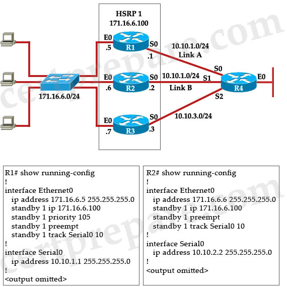
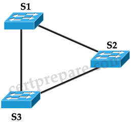
In this topology, R1 is the active router for Group 1 and is the standby router for Group 2 while R2 is the active router for Group 2 and is the standby router for Group 1. The configurations of R1 and R2 are shown below:

R1:
interface fa0/1 //Group 1
ip address 192.168.1.2
standby 1 ip 192.168.1.1
standby 1 priority 150
standby 1 preempt
standby 1 track Serial 0
!
interface fa0/0 //Group 2
ip address 192.168.2.2
standby 2 ip 192.168.2.1
standby 2 priority 145
standby 2 preempt
R2:
interface fa0/1 //Group 2
ip address 192.168.2.3
standby 2 ip 192.168.2.1
standby 2 priority 150
standby 2 preempt
standby 2 track Serial 0
!
interface fa0/0 //Group 1
ip address 192.168.1.3
standby 1 ip 192.168.1.1
standby 1 priority 145
standby 1 preempt

-> C is correct.

Note: An interface can belong to multiple HSRP groups, and the same HSRP group can be applied to different interfaces -> E is not correct.

Question 2

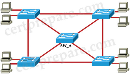
Refer to the exhibit. Assume that Switch_ A is active for the standby group and the standby device has only the default HSRP configuration. What conclusion is valid?

Switch_A(config-if)# ip address 10.10.10.1 255.255.255.0
Switch_A(config-if)# standby 1 priority 200
Switch_A(config-if)# standby 1 preempt
Switch_A(config-if)# standby 1 track interface fa 1/1
Switch_A(config-if)# standby 1 ip 10.10.10.10

A. If port Fa1/1 on Switch_ A goes down, the standby device will take over as active.
B. If the current standby device were to have the higher priority value, it would take over the role of active for the HSRP group.
C. If port Fa1/1 on Switch_ A goes down, the new priority value for the switch would be 190.
D. If Switch_ A had the highest priority number, it would not take over as active router.


Answer: C

Explanation

By default, the standby track interface decrement is 10 so if interface fa1/1 goes down, the new priority value is 200 – 10 = 190

Question 3

Which statement best describes first-hop redundancy protocol status, given the command output in the exhibit?

HSRP_show_ip_arp.jpg

A. The first-hop redundancy protocol is not configured for this interface.
B. HSRP is configured for group 10.
C. HSRP is configured for group 11.
D. VRRP is configured for group 10.
E. VRRP is configured for group 11.
F. GLBP is configured with a single AVF.


Answer: C

Explanation

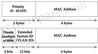
The MAC address of the last IP is 0000.0c07.ac0b indicates HSRP has been configured for group 11 (0b in hexa = 11 in decimal).

Question 4

HSRP has been configured between two Company devices. What kind of message does an HSRP configured router send out every 3 seconds?

A. Retire
B. Coup
C. Resign
D. Send
E. Hello


Answer: E

Question 5

The following command was issued on a router that is being configured as the active HSRP router.
standby ip 10.2.1.1

Which statement is true about this command?

A. This command will not work because the HSRP group information is missing
B. The HSRP MAC address will be 0000.0c07.ac00
C. The HSRP MAC address will be 0000.0c07.ac01
D. The HSRP MAC address will be 0000.070c.ad01
E. This command will not work because the active parameter is missing


Answer: B

Explanation

The full syntax of the command above is:

standby [group-number] ip [ip-address [secondary]]

Therefore in the command “standby ip 10.2.1.1″ we recognize it is using the default group-number, which is 0 -> The last two-digit hex value of HSRP MAC address should be “00″.


Question 6

What can be determined about the HSRP relationship from the displayed debug output?

*Mar 1 00:12:16.871: SB11: Vl11 Hello in 172.16.11.112 Active pri 50 ip 172.16.11.115
*Mar 1 00:12:16.871: SB11: Vl11 Active router is 172.16.11.112
*Mar 1 00:12:18.619: %LINK-3-UPDOWN: Interface Vlan11, changed state to up
*Mar 1 00:12:18.623: SB: Vl11 Interface up
*Mar 1 00:12:18.623: SB11: Vl11 Init: a/HSRP enabled
*Mar t 00:12:18.623: SB11: Vl11 Init-> Listen
*Mar 1 00:12:19.619: %LINEPROTO-5-UPDOWN: Line protocol on Interface Vlan1 1, changed state to up
*Mar 1 00:12:19.819: SB11: Vl11 Hello in 172.16.11.112 Active pri 50 ip 172.16.11.115
*Mar 1 00:12:19.819: SB11: V111 Listen: h/Hello rcvd from lower pri Active router (50/172.16.11.112)
*Mar 1 00:12:22.815: SB11: Vl11 Hello in 172.16.11.112 Active pri 50 ip 172.16.11.115
*Mar 1 00:12:22.815: SB11: Vl11 Listen: h/Hello rcvd from lower pri Active router
*Mar 1 00:12:25.683: SB11: Vl11 Hello in 172.16.11.112 Active pri 50 ip 172.16.11.115
*Mar 1 00:12:25.683: SB11: Vl11 Listen: h/Hello rcvd from lower pri Active router (50/172.16.11.112)
*Mar 1 00:12:28.623: SB11: Vl11 Listen: d/Standby timer expired (unknown)
*Mar 1 00:12:28.623: SB11: Vl11 Listen-> Speak
*Mar 1 00:12:28.623: SB11: Vl11 Hello out 172.16.11.111 Speak pri 100 ip 172.16.11.115
*Mar 1 00:12:28.659: SB11: Vl11 Hello in 172.16.11.112 Active pri 50 ip 172.16.11.115
*Mar 1 00:12:28.659: SB11: Vl11 Speak h/Hello rcvd from lower pri Active router (50/172.16.11.112)
*Mar 1 00:12:31.539: SB11: Vl11 Hello in 172.16.11.112 Active pri 50 ip 172.16.11.115
*Mar 1 00:12:31.539: SB11: Vl11 Speak h/Hello rcvd from lower pri Active router (50/172.16.11.112)
*Mar 1 00:12:31.575: SB11: Vl11 Hello out 172.16.11.111 Speak pri 100 ip 172.16.11.115
*Mar 1 00:12:34.491: SB11: Vl11 Hello in 172.16 11.112 Active pri 50 ip 172.16.11.115

A. Router 172.16.11.112 will be the active router because its HSRP priority is preferred over router 172.16.11.111
B. Router 172.16.11.111 will be the active router because its HSRP priority is preferred over router 172.16.11.112
C. The IP address 172.16.11.111 is the virtual HSRP router IP address.
D. The IP address 172.16.11.112 is the virtual HSRP router IP address.
E. The nonpreempt feature is enabled on the 172.16.11.112 router.
F. The preempt feature is not enabled on the 172.16.11.111 router.


Answer: F

Explanation

To understand the output you should learn these terms:

Field Description
SB Abbreviation for “standby”
Vl11 Interface on which a Hot Standby packet was sent or received.
Hello in Hello packet received from the specified IP address.
Hello out Hello packet sent from the specified IP address.
pri Priority advertised in the hello packet.
ip address Hot Standby group IP address advertised in the hello packet.
state Transition from one state to another.

(Reference: http://www.cisco.com/en/US/docs/ios/debug/command/reference/db_s1.html)

From the output we learn:

Line Debug output Description
1 Vl11 Hello in 172.16.11.112 Active pri 50 ip 172.16.11.115 Priority of 172.16.11.112 is 50 (its standby IP address is 172.16.11.115)
2 Active router is 172.16.11.112 The current active router is 172.16.11.112
3 Interface Vlan11, changed state to up Interface Vlan11 is turned on
6 Init-> Listen Our router changes from Init to Listen state
15 Listen-> Speak After the standby timer expired (line 14), our router changes from Listen to Speak state
16 Hello out 172.16.11.111 Speak pri 100 ip 172.16.11.115 Our router IP is 172.16.11.111, priority is 100 (its standby IP address is also 172.16.11.115)
18 Speak h/Hello rcvd from lower pri Active router The Hellos received from lower priority Active router but our router does not send Coup message to take over active state

In short, our router (172.16.11.111) changes from Init -> Listen -> Speak state. It received hellos from the active router 172.16.11.112 with lower priority but it does not send Coup message to take over active state -> It is not configured with the “preempt” command.

Question 7

Refer to the exhibit. Based on the “debug standby” output in the exhibit, which HSRP statement is true?

*May 10 20:34:08.925: *SYS- 5-CONFIG_I: Configured from console by console
*May 10 20:34:10.213: LINK-3-UPDOWN: Interface Vlan11, changed state to up
*May 10 20:34:10.221: SB: Vl11 : Interface up
*May 10 20:34:10.221: SB11: Vl11 Init: a/HSRP enabled
*May 10 20:34:10.221: SB11: Vl11 Init -> Listen
*May 10 20:34:11.213: LINEPROTO-5-UPDOWN: Line protocol on Interface Vlan11 changed state to up
*May 10 20:34:20.221: SB11: Vl11 Listen: c/Active timer expired (unknown)
*May 10 20:34:20.221: SB11: Vl11 Listen -> Speak
*May 10 20:34:20.221: SB11: Vl11 Hello out 10.10.10, 111 Speak pri 100 ip 10.10. 10.115
*May 10 20:34:28.905; SB11: Vl11 Hello out 10.10.10.111 Speak pri 100 ip 10.10. 10.115
*May 10 20:34:30.221: SB11: Vl11 Speak: d/Standby timer expired (unknown)
*May 10 20:34:30.221: SB11: Vl11 Standby router is local
*May 10 20:34:30.221; SB11: Vl11 Speak -> Standby
*May 10 20:34:30.221; SB11: Vl11 Hello out 10.10.10.111 Standby pri 100 ip 10.10. 10.115
*May 10 20:34:30.221: SB11: Vl11 Standby: e/Active timer expired (unknown)
*May 10 20:34:30.221: SB11: Vl11 Active router is local
*May 10 20:34:30.221: SB11: Vl11 Standby router is unknown, was local
*May 10 20:34:30.221: SB11: Vl11 Standby -> Active
*May 10 20:34:30.221: %STANDBY-6- STATECHANGE: Vlan11 Group 11 state Standby -> Active
*May 10 20:34:30.221: SB11: Vl11 Hello out 10.10.10.111 Active pri 100 ip 10.10. 10.115
*May 10 20:34:33.085: SB11: Vl11 Hello out 10.10.10.111 Active pri 100 ip 10.10. 10.115

A. DSW111 is the active router because it is the only HSRP-enabled router on that segment.
B. DSW111 is the active router because the standby timer has been incorrectly configured.
C. DSW111 is the active router because it has a lower priority on that VLAN.
D. DSW111 is the active router because it has a lower IP address on that VLAN.
E. DSW111 is the active router and is advertising the virtual IP address 10.10.10.111 on VLAN 11.


Answer: A

Explanation

From the output we learn that DSW111 moves from Init -> Listen -> Speak -> Standby -> Active and all the messages are “Hello out” (no messages are “Hello in”). This means that DSW111 is the only router sending messages in this segment.

(If you don’t know about these terms please read the explanation of Question 6)

Question 8

Refer to the exhibit. Based on the debug output shown in the exhibit, which three statements about HSRP are true? (Choose three.)

*Mar 1 00 16:43.095: %LINK-3-UPDOWN: Interface Vlan11, changed state to up
*Mar 1 00 16:43.099: SB: Vl11 Interface up
*Mar 1 00 16:43.099: SB11: Vl11 Init: a/HSRP enabled
*Mar 1 00 16:43.099: SB11: Vl11 Init -> Listen
*Mar 1 00 16:43.295: SB11: Vl11 Hello in 172.16.11.112 Active pri 50 ip 172.16.11.115
*Mar 1 00 16:43.295: SB11: Vl11 Active router is 172.16.11.112
*Mar 1 00 16:43.295: SB11: Vl11 Listen: h/Hello rcvd from lower pri Active router (50/172.16.11.112)
*Mar 1 o o 16:43.295: SB11: Vl11 Active router is local, was 172.16.11.112
*Mar 1 00 16:43.299: %STANDBY-6-STATECHANGE: Vlan11 Group 11 state Listen -> Active
*Mar 1 00 16:43.299: SB11: Vl11 Hello out 172.16.11.111 Active pri 100 ip 172.16.11.115
*Mar 1 00 16:43.303: SB11: Vl11 Hello in 172.16.11.112 Speak pri 50 ip 172.16.11.115
*Mar 1 00 16:46.207: SB11: Vl11 Hello out 172.16.11.111 Active pri 100 ip 172.16.11.115
*Mar 1 00 16:49.095: SB11: Vl11 Hello in 172.16.11.112 Speak pri 50 ip 172.16.11.115

A. The router with IP address 172.16.11.111 has preempt configured.
B. The final active router is the router with IP address 172.16.11.111.
C. The router with IP address 172.16.11.112 has nonpreempt configured.
D. The priority of the router with IP address 172.16.11.112 is preferred over the router with IP address 172.16.11.111.
E. The router with IP address 172.16.11.112 is using default HSRP priority.
F. The IP address 172.16.11.116 is the virtual HSRP IP address.


Answer: A B F

Question 9

HSRP_show_standby.jpg

Examine the router output above. Which two items are correct? (Choose two)

A. The local IP address of Router A is 10.1.0.6.
B. The local IP address of Router A is 10.1.0.20.
C. If Ethernet 0/2 goes down, the standby router will take over.
D. When Ethernet 0/3 of RouterA comes back up, the priority will become 105.
E. Router A will assume the active state if its priority is the highest.


Answer: D E

The current state of this router is “active” and the standby router is 10.1.0.6, which makes answer A incorrect)

The IP address of the local router is not mentioned so we can’t conclude answer B. Notice that the IP 10.1.0.20 is just the virtual IP address of this HSRP group.

+ “Tracking 2 objects, 0 up” -> both Ethernet0/2 and 0/3 are currently down so the priority of RouterA was reduced from 120 to 95 (120 – 15 – 10). Therefore when Ethernet0/3 is up again, the priority of RouterA will be 95 + 10 = 105 -> D is correct.

From the line “preempt enabled” we learn this router is configured with “preempt” command so it will take over the active state if its priority is the highest -> E is correct. But a funny thing in this question is even when two interfaces are down, the priority of RouterA is still higher than the standby router so it is still the active router (the priority of standby router is 75). This also makes answer C incorrect.

Question 10

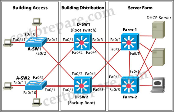
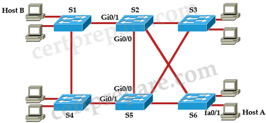
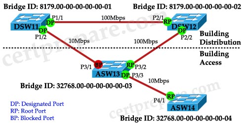
Refer to the exhibit. On the basis of the information provided in the exhibit, which two sets of procedures are best practices for Layer 2 and 3 failover alignment? (Choose two)

HSRP_STP.jpg

A. Configure the D-SW1 switch as the active HSRP router and the STP root for all VLANs. Configure the D-SW2 switch as the standby HSRP router and backup STP root for all VLANs.
B. Configure the D-SW1 switch as the standby HSRP router and the STP root for VLANs 11 and 110. Configure the D-SW2 switch as the standby HSRP router and the STP root for VLANs 12 and 120.
C. Configure the D-SW1 switch as the active HSRP router and the STP root for VLANs 11 and 110. Configure the D-SW2 switch as the active HSRP router and the STP root for VLANs 12 and 120.
D. Configure the D-SW2 switch as the active HSRP router and the STP root for all VLANs. Configure the D-SW1 switch as the standby HSRP router and backup STP root for all VLANs.
E. Configure the D-SW1 switch as the active HSRP router and the backup STP root for VLANs 11 and 110. Configure the D-SW2 switch as the active HSRP router and the backup STP root for VLANs 12 and 120.
F. Configure the D-SW1 switch as the standby HSRP router and the backup STP root for VLANs 12 and 120. Configure the D-SW2 switch as the standby HSRP router and the backup STP root for VLANs 11 and 110.


Answer: C F

Explanation

The “best practices for Layer 2 and 3 failover alignment” here means using load sharing of HSRP.

To load sharing with HSRP, we can divide traffic into two HSRP groups:

+ One group assigns the active state for one switch
+ The other group assigns the active state for the other switch

-> C and F are correct.

Also please read an example of HSRP load sharing in the explanation of Question 1 on this page.


HSRP Questions 2

$
0
0

Here you will find answers to HSRP Questions – Part 2

Question 1

Three Cisco Catalyst switches have been configured with a first-hop redundancy protocol. While reviewing some show commands, debug output, and the syslog, you discover the following information:

Jan 9 08:00:42.623: %STANDBY-6-STATECHANGE: Standby: 49:
Vlan149 state Standby -> Active
Jan 9 08:00:56.011: %STANDBY-6-STATECHANGE: Standby: 49:
Vlan149 state Active -> Speak
Jan 9 08:01:03.011: %STANDBY-6-STATECHANGE: Standby: 49:
Vlan149 state Speak -> Standby
Jan 9 08:01:29.427: %STANDBY-6-STATECHANGE: Standby: 49:
Vlan149 state Standby -> Active
Jan 9 08:01:36.808: %STANDBY-6-STATECHANGE: Standby: 49:
Vlan149 state Active -> Speak
Jan 9 08:01:43.808: %STANDBY-6-STATECHANGE: Standby: 49:
Vlan149 state Speak -> Standby

What conclusion can you infer from this information?

A. VRRP is initializing and operating correctly.
B. HSRP is initializing and operating correctly.
C. GLBP is initializing and operating correctly.
D. VRRP is not properly exchanging three hello messages.
E. HSRP is not properly exchanging three hello messages.
F. GLBP is not properly exchanging three hello messages.


Answer: E

Explanation

These error messages describe a situation in which a standby HSRP router did not receive three successive HSRP hello packets from its HSRP peer (by default, hello messages are sent every 3 seconds while the holdtime is 10 seconds). The output shows that the standby router moves from the standby state to the active state. Shortly thereafter, the router returns to the standby state. Unless this error message occurs during the initial installation, an HSRP issue probably does not cause the error message. The error messages signify the loss of HSRP hellos between the peers. When you troubleshoot this issue, you must verify the communication between the HSRP peers. A random, momentary loss of data communication between the peers is the most common problem that results in these messages. HSRP state changes are often due to High CPU Utilization. If the error message is due to high CPU utilization, put a sniffer on the network and the trace the system that causes the high CPU utilization.

(Reference and good resource: http://www.cisco.com/en/US/tech/tk648/tk362/technologies_tech_note09186a0080094afd.shtml)

Question 2

You administer a network that uses two routers, R1 and R2, configured as an HSRP group to provide redundancy for the gateway. Router R1 is the active router and has been configured as follows:

R1#configure terminal
R1(config)#interface fa0/0
R1(config-if)#ip address 10.10.0.5 255.255.255.0
R1(config-if)#standby 1 priority 150
R1(config-if)#standby preempt delay minimum 50
R1(config-if)#standby 1 track interface fa0/2 15
R1(config-if)#standby 1 ip 10.10.0.20

Which of the following describes the effect the “standby preempt delay minimum 50” command will have on router R1?

A. The HSRP priority for router R1 will increase to 200.
B. Router R1 will become the standby router if the priority drops below 50.
C. The HSRP priority for router R1 will decrease to 50 points when FaO/2 goes down.
D. Router R1 will wait 50 seconds before attempting to preempt the active router.


Answer: D

Explanation

If R1, for some reason, loses its active state, the “standby preempt delay minimum 50″ command will cause R1 to wait 50 seconds before it tries to get the active state again -> D is correct.

Question 3

Refer to the exhibit. HSRP has been configured and Link A is the primary route to router R4. When Link A fails, router R2 (Link B) becomes the active router. Which router will assume the active role when Link A becomes operational again?

HSRP_active_standby.jpg

A. The primary router R1 will reassume the active role when it comes back online.
B. The standby router R2 will remain active and will forward the active role to router R1 only in the event of its own failure.
C. The standby router R2 will remain active and will forward the active role to router R1 only in the event of Link B failure.
D. The third member of the HSRP group, router R3, will take over the active role only in event of router R2 failure.


Answer: A

Explanation

When R1 fails, the “standby 1 preempt” command on R2 will cause R2 to take over the active state of R1. But when R1 comes up again, the “standby 1 preempt” command on R1 will help R1 take over the active state again. Without the “preempt” command configured on R2, R2 only takes over the active state only if it receives information indicating that there is no router currently in active state (by default it does not receive 3 hello messages from the active router). Without the “preempt” command on R2, it will not become active router even if its priority is higher than all other routers.

Question 4

Which first-hop redundancy solution listed would supply clients with MAC address 0000.0C07.AC0A for group 10 in response to an ARP request for a default gateway?

A. IRDP
B. Proxy ARP
C. GLBP
D. HSRP
E. VRRP
F. IP Redirects


Answer: D

Explanation

The last two-digit hex value in the MAC address presents the HSRP group number. In this case 0A in hexa equals 10 in decimal so this router belongs to group 10 and it is running HSRP.

Question 5

What three tasks must a network administrator perform to properly configure Hot Standby Routing Protocol (HSRP)? (Choose three)

A. Define the encapsulation type.
B. Define the standby router.
C. Define the standby IP address.
D. Enable the standby priority.


Answer: B C D

Question 6

You want to allow Router R1 to immediately become the active router if its priority is highest than the active router fails. What command would you use if you wanted to configure this?

A. en standby 1 preempt
B. standby 1 preempt enable
C. standby 1 preempt
D. hot standby 1 preempt


Answer: C

Question 7

Routers R1 and R2 are configured for HSRP as shown below:

Router R1:

interface ethernet 0
ip address 20.6.2.1 255.255.255.0
standby 35 ip 20.6.2.21
standby 35 priority 100
interface ethernet 1
ip address 20.6.1.1 255.255.255.0
standby 34 ip 20.6.1.21

Router R2:

interface ethernet 0
ip address 20.6.2.2 255.255.255.0
standby 35 ip 20.6.2.1
interface ethernet 1
ip address 20.6.1.2 255.255.255.0
standby 34 ip 20.6.1.21
standby 34 priority 100

You have configured the routers R1 & R2 with HSRP. While debugging router R2 you notice very frequent HSRP group state transitions. What is the most likely cause of this?

A. physical layer issues
B. no spanning tree loops
C. use of non-default HSRP timers
D. failure to set the command standby 35 preempt


Answer: A

Explanation

Both routers are not configured with the “preempt” command so by default they only take over the active state when they believe there is no active router (by default they don’t hear 3 successive hello messages from the active router). Therefore the most likely cause of this problem is a link failure between them (physical layer issue) -> A is correct.

Question 8

In which three HSRP states do routers send hello messages? (Choose three)

A. Learn
B. Speak
C. Standby
D. Listen
E. Active
F. Remove


Answer: B C E

Explanation

Speak state: sends hello messages to compete for the standby or active role.
Standby state: send hello messages to inform it is the standby router so that other routers (which are not active or standby router, in listen state) know the standby router is still there.
Active state: sends hello messages to indicate it is still up

Question 9

In the hardware address 0000.0c07.ac0a, what does 07.ac represent?

A. HSRP well-known physical MAC address
B. Vendor code
C. HSRP router number
D. HSRP group number
E. HSRP well-known virtual MAC address


Answer: E

Explanation

The HSRP standby IP address is a virtual MAC address which is composed of 0000.0c07.ac**. In which “**” is the HSRP group number in hexadecimal.

Question 10

Refer to the exhibit. Which two problems are the most likely cause of the exhibited output? (Choose two)

Vlan8 – Group 8
Local state is Active, priority 110, may preempt
Hellotime 3 holdtime 10
Next hello sent in 00:00:01.168
Hot standby IP address is 10.1.2.2 configured
Active router is local
Standby router is unknown expired
Standby virtual mac address is 0000.0c07.ac08
5 state changes, last state change 00:05:03

A. Transport layer issues
B. VRRP misconfiguration
C. HSRP misconfiguration
D. Physical layer issues
E. Spanning tree issues


Answer: C D

Explanation

When you see this error, it means the local router fails to receive HSRP hellos from neighbor router. Two things you should check first are the physical layer connectivity and verify the HSRP configuration. An example of HSRP misconfiguration is the mismatched of HSRP standby group and standby IP address.

Another thing you should check is the mismatched VTP modes.

(Reference: http://www.cisco.com/en/US/tech/tk648/tk362/technologies_tech_note09186a0080094afd.shtml)

HSRP Questions

$
0
0

Here you will find answers to Hot Standby Router Protocol (HSRP) Questions

Question 1

Which protocol specified by RFC 2281 provides network redundancy for IP networks, ensuring that user traffic immediately and transparently recovers from first-hop failures in network edge devices or access circuits?

A. ICMP
B. IRDP
C. HSRP
D. STP


Answer: C

Explanation

HSRP is a Cisco-proprietary protocol developed to allow several routers or multilayer switches to appear as a single gateway IP address. This protocol is described in RFC 2281.

Question 2

Which of the following HSRP router states does an active router enter when it is preempted by a higher priority router?

A. active
B. speak
C. learn
D. listen
E. init
F. standby


Answer: B

Explanation

First we should review all the HSRP States:

State Description
Initial This is the beginning state. It indicates HSRP is not running. It happens when the configuration changes or the interface is first turned on
Listen The router knows both IP and MAC address of the virtual router but it is not the active or standby router. For example, if there are 3 routers in HSRP group, the router which is not in active or standby state will remain in listen state.
Speak The router sends periodic HSRP hellos and participates in the election of the active or standby router.
Standby In this state, the router monitors hellos from the active router and it will take the active state when the current active router fails (no packets heard from active router)
Active The router forwards packets that are sent to the HSRP group. The router also sends periodic hello messages

Now let’s take an example of a router passing through these states. Suppose there are 2 routers A and B in the network; router A is turned on first. It enters the initial state. Then it moves to listen state in which it tries to hear if there are already active or standby routers for this group. After learning no one take the active or standby state, it determines to take part in the election by moving to speak state. Now it starts sending hello messages containing its priority. These messages are sent to the multicast address 224.0.0.2 (which can be heard by all members in that group). When it does not hear a hello message with a higher priority it assumes the role of active router and moves to active state. In this state, it continues sending out periodic hello messages.

Now router B is turned on. It also goes through initial and listen state. In listen state, it learns that router A has been already the active router and no other router is taking standby role so it enters speak state to compete for the standby router -> it promotes itself as standby router.

Now to our main question! We want router B to become active router so we set a higher priority number than the priority of A and ask router B to take over the role of active router (with the preempt command). Now router A will fall back to the speak state to compete for active or standby state -> it becomes standby router because its priority is now lower than that of router A. (Therefore answer B is correct).

Note: Suppose router A is in active state while router B is in standby state. If router B does not hear hello messages from router A within the holdtime, router B goes into speak state to announce its priority to all HSRP members and compete for the active state. But if at some time it receives a message from the active router that has a lower priority than its priority (because the administrator change the priority in either router), it can take over the active role by sending out a hello packet with parameters indicating it wants to take over the active router. This is called a coup hello message.

(Reference and good resource: http://www.cisco.com/en/US/tech/tk648/tk362/technologies_tech_note09186a0080094a91.shtml)

Question 3

Which three statements are true of a default HSRP configuration? (Choose three)

A. The Standby hello time is 2 seconds.
B. Two HSRP groups are configured.
C. The Standby track interface priority decrement is 10.
D. The Standby hold time is 10 seconds
E. The Standby priority is 100.
F. The Standby delay is 3 seconds.


Answer: C D E

Explanation

The table below shows the default values of popular HSRP parameters:

Feature Default Setting
Standby group number 0
Standby MAC address System assigned as: 0000.0c07.acXX, where XX is the HSRP group number
Standby priority 100
Standby delay 0 (no delay)
Standby track interface priority 10
Standby hello time 3 seconds
Standby holdtime 10 seconds

Note:

* Standby delay: If router A is the HSRP active router and then loses a link, which causes it to become standby router, and then the link comes back, the delay command causes router A to wait before it becomes active again. For example, with the “standby preempt delay minimum 30” command, it waits for 30 seconds for the router to become active.

* Standby track: For example, consider this configuration:
standby priority 150
standby track serial 0

An HSRP priority of 150 is configured with the standby priority command and HSRP is configured to track the state of interface Serial0. Because no decrement value is specified in the standby track command, the HSRP priority is decremented by the default value of 10 when the tracked interface goes down.

(Reference: http://www.cisco.com/en/US/docs/switches/lan/catalyst3550/software/release/12.1_12c_ea1/configuration/guide/swhsrp.html)

Question 4

hostname Switch1
interface Vlan10
ip address 172.16.10.32 255.255.255.0
no ip redirects
standby 1 ip 172.16.10.110
standby 1 timers 1 5
standby 1 priority 130
hostname Switch2
interface Vlan10
ip address 172.16.10.33 255.255.255.0
no ip redirects
standby 1 ip 172.16.10.110
standby 1 timers 1 5
standby 1 priority 120

HSRP was implemented and configured on two switches while scheduled network maintenance was performed.
After the two switches have finished rebooting, you notice via show commands that Switch2 is the HSRP active router. Which two items are most likely the cause of Switch1 not becoming the active router? (Choose two)

A. booting delays
B. standby group number does not match VLAN number
C. IP addressing is incorrect
D. premption is disabled
E. incorrect standby timers
F. IP redirect is disabled


Answer: A D

Explanation

When two routers are turned on at the same time, the router completes booting process first will take the active role. Without the “preempt” configured, even a new router with a higher priority cannot take over the active role.In the configuration of Switch1 we don’t see the “preempt” command configured.

Question 5

hostname Switch1
interface Vlan10
ip address 172.16.10.32 255.255.255.0
no ip redirects
standby 1 ip 172.16.10.110
standby 1 timers msec 200 msec 700
standby 1 preempt
hostname Switch2
interface Vlan10
ip address 172.16.10.33 255.255.255.0
no ip redirects
standby 1 ip 172.16.10.110
standby 1 timers msec 200 msec 750
standby 1 priority 110
standby 1 preempt
hostname Switch3
interface Vlan10
ip address 172.16.10.34 255.255.255.0
no ip redirects
standby 1 ip 172.16.10.110
standby 1 timers msec 200 msec 750
standby 1 priority 150
standby 1 preempt

Refer to the exhibit. Three switches are configured for HSRP. Switch1 remains in the HSRP listen state. What is the most likely cause of this status?

A. this is normal operation
B. standby group number does not match VLAN number
C. IP addressing is incorrect
D. incorrect priority commands
E. incorrect standby timers


Answer: A

Explanation

Only Switch 1 is not configured with the priority so it will have the default priority of 100, which is smaller than that of Switch2 (110) and Switch3 (150). Moreover, both Switch2 and Switch3 have the “preempt” command so surely Switch3 becomes active router while Switch2 becomes standby router -> Switch1 will be in listen state (Please read the explanation of question 2 to understand more about this state).

Question 6

What are three possible router states of HSRP routers on a LAN? (Choose three)

A. Standby
B. Established
C. Active
D. Idle
E. Backup
F. Init


Answer: A C F

Explanation

Same as Question 2

Question 7

Refer to the exhibit. Which configuration on the HSRP neighboring device ensures that it becomes the active HSRP device in the event that port fa1/1 on Switch_A goes down?

Switch_A(config-if)# ip address 10.10.10.1 255.255.255.0
Switch_A(config-if)# standby 1 priority 200
Switch_A(config-if)# standby 1 preempt
Switch_A(config-if)# standby 1 track interface fa 1/1
Switch_A(config-if)# standby 1 ip 10.10.10.10

A.
Switch_B(config-if)#ip address 10.10.10.2 255.255.255.0
Switch_B(config-if)#standby 1 priority 200
Switch_B(config-if)#standby 1 preempt
Switch_B(config-if)#standby 1 ip 10.10.10.10
Switch_B(config-if)#standby 1 track interface fa 1/1

B.
Switch_B(config-if)#ip address 10.10.10.2 255.255.255.0
Switch_B(config-if)#standby 1 priority 200
Switch_B(config-if)#standby 1 ip 10.10.10.10

C.
Switch_B(config-if)#ip address 10.10.10.2 255.255.255.0
Switch_B(config-if)#standby 1 priority 195
Switch_B(config-if)#standby 1 preempt
Switch_B(config-if)#standby 1 ip 10.10.10.10

D.
Switch_B(config-if)#ip address 10.10.10.2 255.255.255.0
Switch_B(config-if)#standby 1 priority 190
Switch_B(config-if)#standby 1 ip 10.10.10.10
Switch_B(config-if)#standby 1 track interface fa 1/1


Answer: C

Explanation

Switch_A is not configured standby track priority value so it will use the default track priority of 10 -> When Switch_A goes down, its priority is 200 – 10 = 190 so Switch_B must be configured with a priority higher than 190. Also Switch_B must have the “preempt” command configured to take over the active state -> C is correct.

Note: Answer A is not correct because Switch_B has the same priority value of Switch_A, but the Switch_B’s ip address on the HSRP interface is higher (10.10.10.2 is higher than 10.10.10.1) so Switch_B will take over the active state of Switch_A even when Switch_A is still operational.

Question 8

Which two statements about the HSRP priority are true? (Choose two)

A. To assign the HSRP router priority in a standby group, the standby group-number priority priority-value global configuration command must be used.
B. The default priority of a router is zero (0).
C. The no standby priority command assigns a priority of 100 to the router.
D. Assuming that preempting has also been configured, the router with the lowest priority in an HSRP group would become the active router.
E. When two routers in an HSRP standby group are configured with identical priorities, the router with the highest configured IP address will become the active router.


Answer: C E

Explanation

The “no standby priority” command will reset the priority to the default value (100) -> C is correct.

To understand answer E please read the explanation of Question 7.

Question 9

HSRP has been configured between two Company devices. Which of the following describe reasons for deploying HSRP? (Choose three)

A. HSRP provides redundancy and fault tolerance
B. HSRP allows one router to automatically assume the function of the second router if the second router fails
C. HSRP allows one router to automatically assume the function of the second router if the second router starts
D. HSRP provides redundancy and load balancing


Answer: A B D

Explanation

Answer A and B are correct because they are the functions of HSRP. I just want to mention about answer D. In fact answer D is not totally correct, in SWITCH only GLBP has the load-balancing feature. HSRP can only load-sharing by configuring some different HSRP groups. But answer D is the only choice left in this question so we have to choose it.

Question 10

Regarding high availability, with the MAC address 0000.0c07.ac03, what does the “03″ represent?

A. The GLBP group number
B. The type of encapsulation
C. The HSRP router number
D. The VRRP group number
E. The HSRP group number
F. The active router number


Answer: E

Explanation

The last two-digit hex value in the MAC address presents the HSRP group number.

Voice Support Questions

$
0
0

Here you will find answers to Voice Support Questions

(Questions 1 to 4 use the same picture)

Question 1:

You work as a network technician, study the exhibit carefully. What is the effect on the trust boundary of configuring the command mls qos trust cos on the switch port that is connected to the IP phone?

ip_phone.jpg

A – Effectively the trust boundary has been moved to the IP phone.
B – The host is now establishing the CoS value and has effectively become the trust boundary.
C – The switch SW is rewriting packets it receives from the IP phone and determining the CoS value.
D – The switch SW will no longer tag incoming voice packets and will trust the distribution layer switch to set the CoS.


Answer: A

Explanation:

The “mls qos trust cos” command is used to configure the port trust state (by default, the port is not trusted). By using this command, you can configure the switch port to which the telephone is connected to trust the CoS labels of all traffic received on that port.

(Note: All current Cisco IP Phones include an internal three-port Layer 2 switch therefore you can think an IP Phone as a switch and network administrators generally accept a Cisco IP Phone as a trusted device.)

Question 2:

If you are a network technician, study the exhibit carefully. Which switch interface configuration command would automatically configure quality of service (QoS) for voice over IP (VoIP) within a QoS domain?

A. auto qos voip cisco-phone
B. mls qos trust
C. switchport priority extend cos 7
D. switchport priority extend trust


Answer: A

Explanation:

The command “mls qos trust” is used to configure the port trust state (by default, the port is not trusted).

The command “switchport priority extend cos 7″ sets the IP phone port to override the priority received from the PC or the attached device (7 is the highest priority).

The command “switchport priority extend trust” tells the Cisco IP Phone to trust the CoS value of the connected PC without remark all packets sent form PC to CoS 0, by default.

Question 3:

Study the exhibit carefully. Which statement is true about the voice traffic coming to the switch access port that is connected to the IP phone?

A. The voice VLAN must be configured as a native VLAN on the switch.
B. A PC connected to a switch port via an IP phone must support a trunking encapsulation.
C. The traffic on the voice VLAN must be tagged with 802.1p encapsulation in order to coexist on the same LAN segment with a PC.
D. A PC connected to a switch port via an IP phone is unaware of the presence of the phone.


Answer: D

Explanation:

The voice VLAN can be configured over a unique voice VLAN (known as the voice VLAN ID or VVID) or over native VLAN -> A is not correct.

The ports k between PC and IP Phone are always functioned as access-mode switch ports so there is no need to support a trunking encapsulation -> B is not correct.

The traffic on the voice VLAN can be tagged with 802.1p encapsulation or 802.1q encapsulation -> C is not correct.

Most Cisco IP Phone models operate as a three-port switch as shown below. Nowadays, the voice traffic and data traffic will normally be on different IP subnets and the IP Phone is unaware of the presence of the phone.

ip_phone_2.jpg

Question 4:

Study the exhibit carefully. Which statement is true when voice traffic is forwarded on the same VLAN used by the data traffic?

A. Quality of service cannot be applied for the voice traffic.
B. The voice traffic cannot be forwarded to the distribution layer.
C. Port security cannot be enabled on the switch that is attached to the IP phone.
D. The voice traffic cannot use 802.1p priority tagging.


Answer: D

Question 5:

Which two codes are supported by Cisco VoIP equipment?

A. G.701 and G719
B. G.711 and G.729
C. G.721 and G.739
D. G.731 and G.749

Answer: B

Question 6:

Study the exhibit carefully, then tell me what is the problem with this configuration?

show_run.jpg

A – Spanning tree PortFast cannot be configured on a port where a voice VLAN is configured.
B – The switch port must be configured as a trunk.
C – Sticky secure MAC addresses cannot be used on a port when a voice VLAN is configured.
D – Spanning tree PortFast cannot be configured on a port when a sticky secure MAC address is used.


Answer: C

InterVLAN Routing

$
0
0

Here you will find answers to InterVLAN Routing questions

Question 1:

Study the exhibit carefully. Both host stations are part of the same subnet but are in different VLANs. On the basis of the information presented in the exhibit, which statement is true about an attempt to ping from host to host?

samesubnetDifferentVLAN

A – Layer 3 device is needed for the ping command to be successful.
B – A trunk port will need to be configured on the link between SA and SB for the ping command to be successful.
C – The two different hosts will need to be in the same VLAN in order for the ping command to be successful.
D – The ping command will be successful without any further configuration changes.

Answer: D

Explanation:

For two hosts in different VLANs, we must use a layer 3 device to transport packages between them. However, in this case both switches are set in “access” mode therefore the VLAN information sent between them will be set as untagged. Moreover, they are in the same subnet so they can ping each other without a layer 3 device.

Question 2:

Based on the following exhibit, which problem is preventing users on VLAN 100 from pinging addresses on VLAN 200?

routing_interVLAN

A – Native VLAN mismatch.
B – Subinterfaces should be created on Fa0/7 and Fa0/8 on DLS1.
C – Trunking needs to be enabled.
D – The ip routing command is missing on DLS1.

Answer: D

Explanation:

To allow communication between two VLANs, we need to enables Layer 3 routing on the switch with the “ip routing” command. Some flatforms are enabled by default but some are not.

Question 3:

Based on the network diagram and routing table output in the exhibit, which one of these statements is true?

vlan10_20_routing

A – InterVLAN routing has been configured properly, and the workstations have connectivity to each other.
B – InterVLAN routing will not occur since no routing protocol has been configured.
C – Although interVLAN routing is not enabled, both workstations will have connectivity to each other.
D – Although interVLAN routing is enabled, the workstations will not have connectivity to each other.
E – None of the above.

Answer: A

Explanation:

In the output we can see both VLAN10 and VLAN20 are shown up (as networks 10.1.1.0 and 10.2.2.0) so the routing has been configured properly. Notice that the “C” letter indicates that these networks are directly connected with the router.

Question 4:

Study the following exhibit carefully, what is the reason that users from VLAN 100 can’t ping users on VLAN 200?

inter_Routing

A – IP routing needs to be enabled on the switch
B – Trunking needs to be enabled on Fa0/1
C – VLAN 1 needs the no shutdown command
D – The native VLAN is wrong

Answer: B

Explanation:

The Fa0/1 interface on the switch is not configured with trunking mode. It needs to be configured as shown below:

SA(config)#interface Fa0/1
SA(config-if)#switchport mode trunk
SA(config-if)#switchport trunk encapsulation dot1q

Question 5:

Assume that a host sends a packet to a destination IP address and that the CEF-based switch does not yet have a valid MAC address for the destination. How is the ARP entry (MAC address) of the next-hop destination in the FIB get?

A – The sending host must send an ARP request for it
B – All packets to the destination are dropped
C – The Layer 3 forwarding engine (CEF hardware) must send an ARP request for it
D – CEF must wait until the Layer 3 engine sends an ARP request for it

Answer: D

Explanation:

If a valid MAC address for the destination is not found, the Layer 3 forwarding engine can’t forward the packet in hardware due to the missing Layer 2 next-hop address. Therefore the packet is sent to the Layer 3 Engine so that it can generate an ARP request (this is called the “CEF glean” state)

CEF_ARP

Question 6:

CEF is a complete new routing switch technology . Which two table types are CEF components?(Choose two)

A – adjacency tables
B – caching tables
C – neighbor tables
D – forwarding information base

Answer: A D

EtherChannel Questions

$
0
0

Here you will find answers to EtherChannel Questions

Notes:

The Port Aggregation Protocol (PAgP) and Link Aggregation Control Protocol (LACP) facilitate the automatic creation of EtherChannels by exchanging packets between Ethernet interfaces. The Port Aggregation Protocol (PAgP) is a Cisco-proprietary solution, and the Link Aggregation Control Protocol (LACP) is standards based.

LACP modes:

+ on: the link aggregation is forced to be formed without any LACP negotiation. A port-channel is formed only if the peer port is also in “on” mode.
+ off: disable LACP and prevent ports to form a port-channel
+ passive: the switch does not initiate the channel, but does understand incoming LACP packets
+ active: send LACP packets and willing to form a port-channel

PAgP modes:

+ on: The link aggregation is forced to be formed without any PAgP negotiation. A port-channel is formed only if the peer port is also in “on” mode.
+ off: disable PAgP and prevent ports to form a port-channel
+ desirable: send PAgP packets and willing to form a port-channel
+ auto: does not start PAgP packet negotiation but responds to PAgP packets it receives

An EtherChannel in Cisco can be defined as a Layer 2 EtherChannel or a Layer 3 EtherChannel.
+ For Layer 2 EtherChannel, physical ports are placed into an EtherChannel group. A logical port-channel interface will be created automatically. An example of configuring Layer 2 EtherChannel can be found in Question 1 in this article.

+ For Layer 3 EtherChannel, a Layer 3 Switch Virtual Interface (SVI) is created and then the physical ports are bound into this Layer 3 SVI. An example of configuring Layer 3 EtherChannel can be found in Question 6 in this article.

Question 1

Refer to the exhibit. LACP has been configured on Switch1 as shown. Which is the correct command set to configure LACP on Switch2?

LACP_channel-group.jpg

A.
Switch2# configure terminal
Switch2(config)# interface range gigabitethernet3/1 -2
Switch2(config-if)# channel-group 5 mode auto

B.
Switch2# configure terminal
Switch2(config)# interface range gigabitethemet3/1 -2
Switch2(config-if)# channel-group 5 mode passive

C.
Switch2# configure terminal
Switch2(config)# interface range gigabitethernet3/1 -2
Switch2(config-if)# channel-group 5 mode desirable

D.
Switch2# configure terminal
Switch2(config)# interface range gigabitethernet3/1 -2
Switch2(config-if)# channel-group 5 mode on


Answer: B

Explanation

LACP trunking supports four modes of operation, as follows:
* On: The link aggregation is forced to be formed without any LACP negotiation. In other words, the switch will neither send the LACP packet nor process any incoming LACP packet. This is similar to the on state for PAgP.
* Off: The link aggregation will not be formed. We do not send or understand the LACP packet. This is similar to the off state for PAgP.
* Passive: The switch does not initiate the channel, but does understand incoming LACP packets. The peer (in active state) initiates negotiation (by sending out an LACP packet) which we receive and reply to, eventually forming the aggregation channel with the peer. This is similar to the auto mode in PAgP.
* Active: We are willing to form an aggregate link, and initiate the negotiation. The link aggregate will be formed if the other end is running in LACP active or passive mode. This is similar to the desirable mode of PAgP.

LACP does not have “auto” & “desirable” modes so A & C are not correct.

Also there are only three valid combinations to run the LACP link aggregate, as follows:

Switch Switch Description
active active Recommended
active passive Link aggregation occurs if negotiation is successful.
on on Link aggregation occurs without LACP. Although this works, it is not recommended.

Therefore if Switch1 is set “active” mode, we cannot set “on” mode on Switch2 -> D is not correct.

Only answer B is suitable in this case.

(Reference: http://www.cisco.com/en/US/tech/tk389/tk213/technologies_configuration_example09186a0080094470.shtml)

An example of configuring Layer 2 EtherChannel using LACP (applied these commands to both switches):

SW(config)#interface range f0/1 – 2
SW(config-if-range)#channel-group 1 mode active

Question 2

Refer to the exhibit. The command switchport mode access is issued on interface FastEthernet0/13 on switch CAT1. What will be the result?

channel-group_switchport-mode-access.jpg

A. The command will be rejected by the switch.
B. Interfaces FastEthernet0/13 and FastEthemet0/14 will no longer be bundled.
C. Dynamic Trunking Protocol will be turned off on interfaces FastEthernet0/13 and FastEthemet0/14.
D. Interfaces FastEthernet0/13 and FastEthernet0/14 will only allow traffic from the native VLAN.
E. Interfaces FastEthernet0/13 and FastEthernet0/14 will continue to pass traffic for VLANs 88,100,360.


Answer: B

Explanation

The default channel protocol in Cisco switches is Port Aggregation Protocol (PAgP). PAgP groups the interfaces with the same speed, duplex mode, native VLAN, VLAN range, and trunking status and type. After grouping the links into an EtherChannel, PAgP adds the group to the spanning tree as a single switch port.

An interface in the on mode that is added to a port channel is forced to have the same characteristics as the already existing on mode interfaces in the channel (applied for both PAgP & LACP). So if we configure “switchport mode access” on Fa0/13, this interface will no longer be bundled with Fa0/14.

(Reference: http://www.cisco.com/en/US/docs/switches/lan/catalyst3550/software/release/12.1_14_ea1/configuration/guide/swethchl.html#wpxref12539)

Question 3

What is the result of entering the command “port-channel load-balance src-dst-ip” on an EtherChannel link?

A. Packets are distributed across the ports in the channel based on both the source and destination MAC addresses.
B. Packets are distributed across the ports in the channel based on both the source and destination IP addresses.
C. Packets are balanced across the ports in the channel based first on the source MAC address, then on the destination MAC address, then on the IP address.
D. Packets are distributed across the access ports in the channel based first on the source IP address and then the destination IP addresses.


Answer: B

Explanation

The syntax of configuring load balancing on a Cisco switch is:

Switch(config)# port-channel load-balance method

Many methods can be used here. By default, the “src-dst-ip” (source and destination IP address) method is used for Layer 3 switching. Let’s take an example to understand more about this method.

EtherChannel_Load_balancing-src-dst-ip.jpg

In the topology above, Switch1 uses the “src-dst-ip” method to load balancing traffic to Switch2. With this method, only one link is used for a specific pair of source & destination IP address and the switch uses the XOR function to generate the hash that is used to determine which interface to use. Suppose the packets have the source IP of 1.1.1.1 & destination IP of 1.1.1.2. Write them in binary we get:

1.1.1.1 = 0000 0001.0000 0001.0000 0001.0000 0001
1.1.1.2 = 0000 0001.0000 0001.0000 0001.0000 0010

In this case we have only 2 interfaces in this channel group so the XOR function only gets the last bit, which means 1 XOR 0 = 1. Each interface is assigned an index that starts from 0 so Fa0/2 will be indexed 1 -> traffic will be sent over Fa0/2.

If we have 4 interfaces in a channel group then XOR function gets last 2 bits. If we have 8 interfaces, it gets 3 bits and so on. For example, with 8 interfaces the result will be 3 (because 001 XOR 010 = 011) -> Fa0/4 will be used.

Note: If the two address values have the same bit value, the XOR result is always 0. If the two address bits differ, the XOR result is always 1. For example, 0 XOR 0 = 0; 0 XOR 1 = 1; 1 XOR 0 = 1; 1 XOR 1 = 0.

In conclusion, the “port-channel load-balance src-dst-ip” command uses a pair of source & destination IP address to select the port to send traffic to -> B is correct.

Question 4

Refer to the exhibit. Which statement is true about the display of the command “show pagp 1 neighbor” command?

show_pagp_neighbor.jpg

A. STP packets are sent out the Gi0/1 interface only.
B. STP packets are sent out both the Gi0/1 and Gi0/2 interfaces.
C. CDP packets are sent out the Gi0/1 interface only.
D. CDP packets are sent out the Gi0/2 interface only.


Answer: A

Explanation

DTP and CDP send and receive packets over all the physical interfaces in the EtherChannel while STP always chooses the first operational port in an EtherChannel bundle -> A is correct.

Question 5

Refer to the exhibit. On the basis of the information that is generated by the show commands, which two EtherChannel statements are true? (Choose two)

show_etherchannel_summary.jpg

A. Interfaces FastEthernet 0/1 and 0/2 have been configured with the channel-group 1 mode desirable command.
B. Interfaces FastEthernet 0/3 and 0/4 have been configured with the no switchport command.
C. Interface Port-Channels 1 and 2 have been assigned IP addresses with the ip address commands.
D. Port-Channels 1 and 2 are providing two 400 Mbps EtherChannels.
E. Port-Channels 1 and 2 are capable of combining up to 8 FastEthernet ports to provide full-duplex bandwidth of up to 16 Gbps between a switch and another switch or host.
F. Switch SW1 has been configured with a Layer 3 EtherChannel.


Answer: A D

Explanation

In fact answer A is not totally correct because two ports Fa0/1 & Fa0/2 of Sw1 can use the “channel-group 1 mode auto” command while the peer ports use the “channel-group 1 mode desirable” command. But maybe it is the best choice in this case.

Answer B is not correct because this is a Layer 2 EtherChannel (from the lines “Po1 (SU)” & “Group state = L2″) but the “no switchport” is only used to configure Layer 3 EtherChannel.

Answer C is not correct because the port-channel is automatically created in a Layer 2 EtherChannel.

In this case we can see the ports are FastEthernet ports -> Port-Channels 1 and 2 are capable of combining up to 8 FastEthernet ports to provide full-duplex bandwidth of up to 1.6 Gbps (8 links of FastEthernet ports), not 16 Gbps. Port-Channels can provide up to 16 Gbps if they group 8 links of GigabitEthernet -> E is not correct.

SW1 has been configured with a Layer 2 EtherChannel (from the lines “Po1 (SU)” & “Group state = L2″) -> F is not correct.

Usually the EtherChannel protocol is shown when using the “show etherchannel summary” command (after the “Port-channel” column) but in this case we see no “protocol” column so we can assume it uses the default EtherChannel protocol PAgP.

There are 2 ports in each group so there are 4 Ethernet ports in total -> 4 x 100Mbps = 400Mbps in full duplex (which means “two 400 Mbps EtherChannels” in answer D) -> D is correct.

Question 6

Which statement is true regarding the Port Aggregation Protocol?

A. Configuration changes made on the port-channel interface apply to all physical ports assigned to the portchannel interface.
B. Configuration changes made on a physical port that is a member of a port-channel interface apply to the port-channel interface.
C. Configuration changes are not permitted with Port Aggregation Protocol; instead, the standardized Link Aggregation Control Protocol should be used if configuration changes are required.
D. The physical port must first be disassociated from the port-channel interface before any configuration changes can be made.


Answer: A

Explanation

The port-channel interface represents for the whole bundle and all the configurations on this interface are applied to all physical ports that are assigned to this logical interface.

Note: We must manually create port-channel logical interface when configuring Layer 3 EtherChannels. The port-channel logical interface is automatically created when configuring Layer 2 EtherChannels (you can’t put Layer 2 ports into a manually created port channel interface).

An example of configuring Layer 3 EtherChannels with port-channel interfaces:

EtherChannel_Load_balancing-src-dst-ip.jpg

Switch1(config)# interface port-channel 1
Switch1(config-if)# no switchport
Switch1(config-if)# ip address 192.168.1.1 255.255.255.0
Switch1(config-if)# exit
Switch1(config)# interface range fastethernet0/1 -2
Switch1(config-if-range)# no switchport
Switch1(config-if-range)# no ip address
Switch1(config-if-range)# channel-group 1 mode desirable
Switch2(config)# interface port-channel 1
Switch2(config-if)# no switchport
Switch2(config-if)# ip address 192.168.1.2 255.255.255.0
Switch2(config-if)# exit
Switch2(config)# interface range fastethernet0/1 -2
Switch2(config-if-range)# no switchport
Switch2(config-if-range)# no ip address
Switch2(config-if-range)# channel-group 1 mode auto

Note: The “no switchport” command is required to change interface from layer2 to layer3 mode.

Question 7

Which three statements are true of the Link Aggregation Control Protocol (LACP)? (Choose three)

A. LACP is used to connect to non-Cisco devices.
B. LACP packets are sent with the command channel-group 1 mode desirable.
C. LACP packets are sent with the command channel-group 1 mode active.
D. Standby interfaces should be configured with a higher priority.
E. Standby interfaces should be configured with a lower priority.


Answer: A C D

Explanation

LACP is part of the IEEE specification 802.3ad so that it can be used on non-Cisco devices -> A is correct.

With mode “active”, the switch will send LACP packets, initiates negotiations with remote ports and willing to form a port-channel if it receives a response -> C is correct.

LACP uses the port priority with the port number to form the port identifier. The port priority determines which ports should be put in standby mode when there is a hardware limitation that prevents all compatible ports from aggregating.

An example of configuring LACP port priority:

Router(config-if)# lacp port-priority 100

Note: Valid range is from 1 to 65535. The higher the number, the lower the priority so standby interfaces should be configured with a higher priority -> D is correct.

Question 8

Refer to the exhibit. What does the command channel-group 1 mode desirable do?

Interface FastEthernet 0/13
Channel-group 1 mode desirable

A. enables LACP unconditionally
B. enables PAgP only if a PAgP device is detected
C. enables PAgP unconditionally
D. enables Etherchannel only
E. enables LACP only if a LACP device is detected


Answer: C

Explanation

First, “desirable” is a mode on PAgP, not LACP. “enable PAgP unconditionally” means that port will send PAgP packets to form an EtherChannel port (initiate negotiations with other ports). A channel is formed with another port group in either desirable or auto mode.

Note:

Mode “auto” enables PAgP only if a PAgP device is detected and mode “on” forces the port to form a channel.

Question 9

Which statement best describes implementing a Layer 3 EtherChannel?

A. EtherChannel is a Layer 2 and not a Layer 3 feature.
B. Implementation requires switchport mode trunk and matching parameters between switches.
C. Implementation requires disabling switchport mode.
D. A Layer 3 address is assigned to the channel-group interface.


Answer: C

Explanation

By default, the ports on a multilayer switch (MLS) will all be running in Layer 2 mode. A port must be configured as a routing port before it is configured as a Layer 3 EtherChannel -> require to use the “no switchport” command.

Private VLAN (PVLAN)

$
0
0

Here you will find answers to Private VLAN Questions

Quick review:

The main purpose of Private VLAN (PVLAN) is to provide the ability to isolate hosts at Layer 2 instead of Layer 3. As you know, a VLAN is a broadcast domain, by using PVLAN we are splitting that domain into some smaller broadcast domains. For example, without PVLAN, a service provider wants to increase security by isolating customers into separate domains so that they can’t access each other, they have to assign them into different VLANs and use different subnets. This can result in a waste of IP addresses and difficulty in VLAN management. Private VLANs (PVLANs) can solve this problem by allowing the isolation of devices at Layer 2 in the same subnet. PVLAN can be considered “VLANs inside VLAN”.

There are three types of ports in PVLAN:

* Isolated: only communicate with promiscuous ports. Notice that it cannot even communicate with another isolated port. Also, there can be only 1 isolated VLAN per PVLAN.
* Promiscuous: can communicate with all other ports. The default gateway is usually connected to this port so that all devices in PVLAN can go outside.
* Community: can communicate with other members of that community and promiscuous ports but cannot communicate with other communities. There can be multiple community VLANs per PVLAN.

PVLAN_Promiscuous_Community_Isolated.jpg

For example, in the topology above:

+ Host A cannot communicate with Host B, C, D, E and F. It can only communicate with Promiscuous port to the router. Notice that even two Isolated ports in the same VLAN cannot communicate with each other.

+ Host C can communicate with Host D because they are in the same community but Host C cannot communicate with E and F because they are in a different community.

+ All hosts can go outside through promiscuous port.

Also I want to mention about the concept of “primary VLAN” and “secondary VLAN”. PVLAN can have only one primary VLAN; all VLANs in a PVLAN domain share the same primary VLAN. Secondary VLANs are isolated or community VLANs.

PVLAN_Primary_VLAN_Secondary_VLAN.jpg

Configuration of PVLAN:

1. Set VTP mode to transparent
2. Create secondary (isolated and community) VLANs and primary VLAN
3. Associate secondary VLANs to the primary VLAN
4. Configure interfaces as promiscuous interfaces
5. Configure interfaces to be isolated or community interfaces.

Sample configuration used the topology above:

//First set VTP to transparent mode
Switch(config)#vtp mode transparent

//Create secondary VLANs
Switch(config)#vlan 101
Switch(config-vlan)#private-vlan isolated
Switch(config-vlan)#vlan 102
Switch(config-vlan)#private-vlan community
Switch(config-vlan)#vlan 103
Switch(config-vlan)#private-vlan community

//Create primary VLAN
Switch(config-vlan)#vlan 100
Switch(config-vlan)#private-vlan primary

//Associate secondary (isolated, community) VLANs to the primary VLAN
Switch(config-vlan)#private-vlan association 101,102,103

//Assign Promiscuous port to the port connected to the router, with the primary VLAN mapped to the secondary VLAN.
Switch(config)# interface f0/1
Switch(config-if)# switchport mode private-vlan promiscuous
Switch(config-if)# switchport private-vlan mapping 100 101,102,103

//Ports connected to hosts A, B, C, D, E, F are configured in host mode and assign to appropriate VLANs (A and B to isolated VLAN 101; C and D to community VLAN 102; E and F to community VLAN 103):
Switch(config)# interface range f0/2 – 0/3 //connect to host A and B
Switch(config-if)# switchport mode private-vlan host
Switch(config-if)# switchport private-vlan host-association 100 101

Switch(config-if)# interface range f0/3 -0/4 //connect to host C and D
Switch(config-if)# switchport mode private-vlan host
Switch(config-if)# switchport private-vlan host-association 100 102

Switch(config-if)# interface f0/5 – 0/6 //connect to host E and F
Switch(config-if)# switchport mode private-vlan host
Switch(config-if)# switchport private-vlan host-association 100 103

To check the configuration, use this command:

Switch# show vlan private-vlan

Question 1

Refer to the exhibit. The web servers WS_1 and WS_2 need to be accessed by external and internal users. For security reasons, the servers should not communicate with each other, although they are located on the same subnet. The servers do need, however, to communicate with a database server located in the inside network. What configuration will isolate the servers from each other?

PVLAN_promiscuous_ports.jpg

A. The switch ports 3/1 and 3/2 will be defined as secondary VLAN community ports. The ports connecting to the two firewalls will be defined as primary VLAN promiscuous ports.
B. The switch ports 3/1 and 3/2 and the ports connecting to the two firewalls will be defined as primary VLAN promiscuous ports.
C. The switch ports 3/1 and 3/2 and the ports connecting to the two firewalls will be defined as primary VLAN community ports.
D. The switch ports 3/1 and 3/2 will be defined as secondary VLAN isolated ports. The ports connecting to the two firewalls will be defined as primary VLAN promiscuous ports.


Answer: D

Explanation

WS_1 and WS_2 cannot communicate with each other so we can put them into isolated ports. Isolated ports can only communicate with promiscuous ports so Fa3/34 and Fa3/35 should be promiscuous ports so that they can send and receive data with the Data Server.

Note: Answer A is not clear because it does not state the switch ports 3/1 and 3/2 are put into the same or different VLAN community ports. If they are put into different VLAN communities then answer A is correct.

Question 2

Refer to the exhibit. What can be concluded about VLANs 200 and 202?

show_vlan_private-vlan_type.jpg

A. VLAN 202 carries traffic from promiscuous ports to isolated, community, and other promiscuous ports in the same VLAN. VLAN 200 carries traffic between community ports and to promiscuous ports.
B. VLAN 202 carries traffic from promiscuous ports to isolated, community, and other promiscuous ports in the same VLAN. VLAN 200 carries traffic from isolated ports to a promiscuous port.
C. VLAN 200 carries traffic from promiscuous ports to isolated, community, and other promiscuous ports in the same VLAN. VLAN 202 carries traffic between community ports and to promiscuous ports.
D. VLAN 200 carries traffic from promiscuous ports to isolated, community, and other promiscuous ports in the same VLAN. VLAN 202 carries traffic from isolated ports to a promiscuous port.


Answer: B

Explanation

In fact the exhibit above is wrong, that output should be from the command “show vlan private-vlan”. The “show vlan private-vlan type” should give output like this:

Vlan
————–
Type
————-
202
200
Primary
isolated

With this output we can see VLAN 202 is configured as the primary VLAN while VLAN 200 is configured as secondary (isolated) VLAN -> B is correct.

Question 3

Private VLANs can be configured as which three of these port types? (Choose three)

A. isolated
B. protected
C. private
D. associated
E. promiscuous
F. community


Answer: A E F

Explanation

There are three types of ports can be configured in a Private VLAN: isolated, promiscuous, community.

* Isolated: only communicate with promiscuous ports. Notice that it cannot even communicate with another isolated port. Also, there can be only 1 isolated VLAN per PVLAN.
* Promiscuous: can communicate with all other ports. The default gateway is usually connected to this port so that all devices in PVLAN can go outside.
* Community: can communicate with other members of that community and promiscuous ports but cannot communicate with other communities. There can be multiple community VLANs per PVLAN.

Question 4

Refer to the exhibit. From the configuration shown, what can you determine about the private VLAN configuration?

Switch# configure terminal
Switch (config)# vlan 20
Switch (config-vlan)# private-vlan primary
Switch (config-vlan)# exit
Switch (config)# vlan 501
Switch (config-vlan)# private-vlan isolated
Switch (config-vlan )#exit
Switch (config)# vlan 502
Switch (config-vlan)#private-vlan community
Switch (config-vlan)# exit
Switch (config)# vlan 503
Switch (config-vlan )# private-vlan community
Switch (config-vlan)# exit
Switch (config)# vlan 20
Switch (config-vlan)#private-vlan association 501-503
Switch (config-vlan)# end

A. Only VLAN 503 will be the community PVLAN because multiple community PVLANs are not allowed.
B. Users of VLANs 501 and 503 will be able to communicate.
C. VLAN 502 is a secondary VLAN.
D. VLAN 502 will be a standalone VLAN because it is not associated with any other VLANs.


Answer: C

Explanation

There are two types of secondary VLAN: isolated and community. In this case VLAN 502 is a community VLAN -> C is correct.

In a PVLAN, multiple community VLANs are allowed. But notice a PVLAN can have only one primary VLAN and one isolated VLAN -> A is not correct.

Only community in the same VLAN can communicate with each other. Users in different communities are not able to communicate -> B is not correct.

The command “private-vlan association 501-503″ associates VLANs 501, 502 and 503 to the Primary VLAN 20 -> D is not correct.

Question 5

When configuring private VLANs, which configuration task must you do first?

A. Configure the private VLAN port parameters.
B. Configure and map the secondary VLAN to the primary VLAN.
C. Disable IGMP snooping.
D. Set the VTP mode to transparent.


Answer: D

Explanation

Before configuring private VLANs, we must set VTP mode to transparent because VTP version 1 and 2 do not support private VLAN (VTP version 3 does support PVLAN). Notice that a switch in VTP transparent mode still forwards other VTP updates to its neighbors.

Question 6

A switch has been configured with Private VLANs. With that type of PVLAN port should the default gateway be configured?

A. Trunk
B. Isolated
C. Primary
D. Community
E. Promiscuous


Answer: E

Explanation

A default gateway should be configured Promiscuous type so that all devices in PVLAN can go outside.

Port Security Questions 2

$
0
0

Here you will find answers to Port Security Questions – Part 2

Question 1

Refer to the exhibit. Based on the running configuration that is shown for interface FastEthemet0/2, what two conclusions can be deduced? (Choose two)

!
interface FastEthernet0/2
switchport mode access
switchport port-security
switchport port-security maximum 6
switchport port-security aging time 5
switchport port-security aging static
switchport port-security mac-address sticky
switchport port-security mac-address 0000.0000.000b
switchport port-security mac-address sticky 0000.0000.4141
switchport port-security mac-address sticky 0000.0000.5050
no ip address

A. Connecting a host with MAC address 0000.0000.4147 will move interface FastEthemet0/2 into error disabled state.
B. The host with address 0000.0000.4141 is removed from the secure address list after 5 seconds of inactivity.
C. The sticky secure MAC addresses are treated as static secure MAC addresses after the running configuration is saved to the startup configuration and the switch is restarted.
D. Interface FastEthemet0/2 is a voice VLAN port.
E. The host with address 0000.0000.000b is removed from the secure address list after 300 seconds.


Answer: C E

Explanation

In this case the “switchport port-security aging time 5″ sets aging time to 5 minutes and the “switchport port-security aging static” tells the switch to age out for statically configured MAC addresses -> the MAC 0000.0000.000b will be aged out after 5 minutes (300 seconds).

Note: Cisco switch does not support port security aging of sticky secure MAC addresses -> the sticky secure MAC addresses are not aged out.

Question 2

Refer to the exhibit. What will happen when one more user is connected to interface FastEthernet 5/1?

show_port-security_interface_fastethernet.jpg

A. The first address learned on the port will be removed from the secure address list and be replaced with the new address.
B. All secure addresses will age out and be removed from the secure address list. This will cause the security violation counter to increment.
C. The packets with the new source addresses will be dropped until a sufficient number of secure MAC addresses are removed from the secure address list.
D. The interface will be placed into the error-disabled state immediately, and an SNMP trap notification will be sent.


Answer: D

Explanation

There are three violation mode of port security:

+ Protect: drop packets (port is not shutdown)
+ Restrict: drop packets and increase violation counter, send SNMP trap notification (port is not shutdown)
+ Shutdown (default mode): put port into error-distabled state (same as shutdown state), send SNMP trap notification

Question 3

When you enable port security on an interface that is also configured with a voice VLAN, what is the maximum number of secure MAC addresses that should be set on the port?

A. No more than one secure MAC address should be set.
B. The default will be set.
C. The IP phone should use a dedicated port, therefore only one MAC address is needed per port.
D. No value is needed if the switchport priority extend command is configured.
E. No more than two secure MAC addresses should be set.


Answer: E

Explanation

Usually, an IP Phone needs two MAC addresses, one for the voice vlan and one for the access vlan. If you don’t want other devices to access this port then you should not set more than two secure MAC addresses.

Below is an example for this configuration:

Switch(config)# interface fa0/1
Switch(config-if)# switchport mode access
Switch(config-if)# switchport port-security
Switch(config-if)# switchport port-security mac-address sticky
Switch(config-if)# switchport port-security maximum 1 vlan voice
Switch(config-if)# switchport port-security maximum 1 vlan access
//Configure static MAC addresses for these VLANs
Switch(config-if)#switchport port-security mac-address sticky 0000.0000.0001
Switch(config-if)#switchport port-security mac-address sticky 0000.0000.0002 vlan voice

(For more information about this, please read http://www.cisco.com/en/US/docs/switches/lan/catalyst4500/12.2/31sg/configuration/guide/port_sec.html)

Question 4

Refer to the exhibit. What type of attack would be mitigated by this configuration?

show_port-security.jpg

A. ARP spoofing
B. MAC spoofing
C. VLAN hopping
D. CDP manipulation
E. MAC flood attack
F. spanning tree compromises


Answer: E

Explanation

The maximum number of hosts allowed is 5 so an attacker can not flood the switch with many source MAC addresses -> This configuration is effective against MAC flooding attack.

Question 5

Refer to the exhibit. Port security has been configured on port Fa0/5. What would happen if another device is connected to the Fa0/5 port after the maximum number of devices has been reached, even if one or more of the original MAC addresses are inactive?

show_run_port_security.jpg

A. The port will permit the new MAC address because one or more of the original MAC addresses are inactive.
B. The port will permit the new MAC address because one or more of the original MAC addresses will age out.
C. Because the new MAC address is not configured on the port, the port will not permit the new MAC address.
D. Although one or more of the original MAC addresses are inactive, the port will not permit the new MAC address.


Answer: D

Explanation

The port-security aging time is set to 0 so it is disabled for this port -> even if the original MAC addresses are inactive, the port will not permit the new MAC address.


Port Security Questions

$
0
0

Here you will find answers to Port Security Questions

Quick review:

Port security feature can be used to limit the number of MAC addresses on a port. It can also allow specific MAC addresses to send traffic into that port.

Question 1

Which of the following should you enable to prevent a switch from forwarding packets with source addresses that are outside an administratively defined group? (Select the best answer)

A. DAI
B. STP
C. PVLAN
D. port security


Answer: D

Explanation

When you assign secure MAC addresses to a secure port, the port does not forward ingress traffic that has source addresses outside the group of defined addresses.

The example below configures secure MAC address 0000.1234.5678. Only traffic from this MAC is forwarded.

Switch(config)# interface fastethernet 0/1
Switch(config-if)# switchport mode access
Switch(config-if)# switchport port-security
Switch(config-if)# switchport port-security mac-address 0000.1234.5678

(Reference: http://www.cisco.com/en/US/docs/switches/lan/catalyst6500/ios/12.2SX/configuration/guide/port_sec.html)

Question 2

You need to configure port security on switch R1. Which two statements are true about this technology? (Choose two)

A. Port security can be configured for ports supporting VoIP.
B. With port security configured, four MAC addresses are allowed by default.
C. The network administrator must manually enter the MAC address for each device in order for the switch to allow connectivity.
D. With port security configured, only one MAC addresses is allowed by default.
E. Port security cannot be configured for ports supporting VoIP.


Answer: A D

Explanation

Port security can be set on ports supporting VoIP. This example shows how to designate a maximum of one MAC address for a voice VLAN (for a Cisco IP Phone) and one MAC address for the data VLAN (for a PC) on Fast Ethernet interface 5/1 and to verify the configuration:
Switch(config)# interface fa5/1
Switch(config-if)# switchport mode access
Switch(config-if)# switchport port-security
Switch(config-if)# switchport port-security mac-address sticky
Switch(config-if)# switchport port-security maximum 1 vlan voice
Switch(config-if)# switchport port-security maximum 1 vlan access

-> A is correct.


By default, only one MAC addresses is allowed but we can use the “switchport port-security maximum number” command to set the maximum number of MAC allowed -> D is correct.

(Reference: http://www.cisco.com/en/US/docs/switches/lan/catalyst4500/12.2/31sg/configuration/guide/port_sec.html)

Question 3

show_port_security_interface.jpg

Refer to the exhibit. The “show port-security interface fa0/1” command was issued on switch SW1. Given the output that was generated, which two security statements are true? (Choose two)

A. Interface FastEthernet 0/1 was configured with the switchport port-security aging command.
B. Interface FastEthernet 0/1 was configured with the switchport port-security protect command.
C. Interface FastEthernet 0/1 was configured with the switchport port-security violation restrict command.
D. When the number of secure IP addresses reaches 10, the interface will immediately shut down.
E. When the number of secure MAC addresses reaches 10, the interface will immediately shut down and an SNMP trap notification will be sent.


Answer: B E (wrong)

Explanation

The “Violation Mode: Protect” tells us this interface has been configured with the switchport port-security protect command. Protect mode drops packets with unknown source addresses when the violation occurs -> B is correct.

Well, I cannot say answer E is correct. There is something wrong here. In “Protect” mode, when the number of secure MAC addresses reaches 10, the interface will not be shut down (it just drops unknown source MAC); also an SNMP trap notification will not be sent (an SNMP would be sent in “Shutdown” or “Restrict” mode). So in the exam you I am sure you will see another version of answer E.

Question 4

Refer to the exhibit. Which interface or interfaces on switch SW_A can have the port security feature enabled?

port_security_ports.jpg

A. Ports 0/1 and 0/2
B. The trunk port 0/22 and the EtherChannel ports
C. Ports 0/1, 0/2 and 0/3
D. Ports 0/1, 0/2, 0/3, the trunk port 0/22 and the EtherChannel ports
E. Port 0/1
F. Ports 0/1, 0/2, 0/3 and the trunk port 0/22


Answer: C

Explanation

Port security can only be configured on static access ports or static trunk ports (DTP disabled). In this case we don’t know if the ports of the trunk link have DTP disabled or not -> only Fa0/1, Fa0/2 and Fa0/3 can be configured port security.

(Reference: http://www.cisco.com/en/US/docs/switches/lan/catalyst2950/software/release/12.1_6_ea2c/configuration/guide/swgports.html)

Question 5

When configuring port security on a Cisco Catalyst switch port, what is the default action taken by the switch if a violation occurs?

A. protect (drop packets with unknown source addresses)
B. restrict (increment SecurityViolation counter)
C. shutdown (access or trunk port)
D. transition (the access port to a trunking port)


Answer: C

Explanation

There are three port security violation modes:
+ protect - Drops packets with unknown source addresses until you remove a sufficient number of secure MAC addresses to drop below the maximum value.
+ restrict - Drops packets with unknown source addresses until you remove a sufficient number of secure MAC addresses to drop below the maximum value and causes the SecurityViolation counter to increment.
+ shutdown - Puts the interface into the error-disabled state immediately and sends an SNMP trap notification.

The default behavior for a security violation is to shut down that port permanently.

(Reference: http://www.cisco.com/en/US/docs/switches/lan/catalyst6500/ios/12.2SX/configuration/guide/port_sec.html)

Question 6

You are responsible for increasing the security within the Company LAN. Of the following choices listed below, which is true regarding layer 2 security and mitigation techniques?

A. Enable root guard to mitigate ARP address spoofing attacks.
B. Configure DHCP spoofing to mitigate ARP address spoofing attacks.
C. Configure PVLANs to mitigate MAC address flooding attacks.
D. Enable root guard to mitigate DHCP spoofing attacks.
E. Configure dynamic APR inspection (DAI) to mitigate IP address spoofing on DHCP untrusted ports.
F. Configure port security to mitigate MAC address flooding.


Answer: F

Explanation

Root guard is used to mitigate Spanning-tree compromises, not ARP address spoofing -> A and D are not correct.

DHCP spoofing is mitigated by DHCP snooping -> B is not correct.

PVLAN is often used to protect devices on a common VLAN, give them more separation even though they are on the same VLAN. It is not used to mitigate MAC address flooding attacks -> C is not correct.

DAI should be used to mitigate ARP Spoofing attack in which the attacker fakes its MAC as the destination MAC to receive traffic intended for valid destination -> E is not correct.

MAC flooding attack is a technique in which the attacker floods the switch with packets, each containing different source MAC address. This makes the switch learn the MAC addresses until its memory is used up. Now the switch acts like a hub, in which all incoming packets are broadcast out on all ports instead of just to the correct destination port as normal operation. The attacker can listen to these broadcast packets and capture sensitive data.

To protect against this type of attack, port security feature can be used to limit and allow specific MAC to access the port -> F is correct. (VLAN Access map with a “mac access list” can also be used to filter MAC).

Question 7

Refer to the exhibit. From the configuration shown, what can be determined?

Switch(config)# interface FastEthemet0/1
Switch(config-if)# switchport access vlan 21
Switch(config-if)# switchport mode access
Switch(config-if)# switchport voice vlan 22
Switch(config-if)# switchport port-security
Switch(config-if)# switchport port-security maximum 20
Switch(config-if)# switchport port-security violation restrict
Switch(config-if)# switchport port-security mac-address sticky
Switch(config-if)# switchport port-security mac-address sticky 0000.0000.0002
Switch(config-if)# switchport port-security mac-address 0000.0000.0003
Switch(config-if)# switchport port-security mac-address sticky 0000.0000.0001 vlan voice
Switch(config-if)# switchport port-security mac-address 0000.0000.0004 vlan voice
Switch(config-if)# switchport port-security maximum 10 vlan access
Switch(config-if)# switchport port-security maximum 10 vlan voice

A. The sticky addresses will only be those manually configured MAC addresses enabled with the sticky keyword.
B. The remaining secure MAC addresses will be dynamically learned, converted to sticky secure MAC addresses, and added to the running configuration.
C. Since a voice VLAN is configured in this example, port security should be set for a maximum of 2.
D. A security violation will restrict the number of addresses to a maximum of 10 addresses per access VLAN and voice VLAN. The port will be shut down if more than 10 devices per VLAN attempt to access the port.


Answer: B

Explanation

The “sticky” keyword in switchport port-security mac-address sticky command converts all the dynamic secure MAC addresses, including those that were dynamically learned before sticky learning was enabled, to sticky secure MAC addresses and adds to the running configuration.

(Reference: http://www.cisco.com/en/US/docs/switches/lan/catalyst3560/software/release/12.2_44_se/configuration/guide/swtrafc.html)

Question 8

What are two methods of mitigating MAC address flooding attacks? (Choose two)

A. Place unused ports in a common VLAN.
B. Implement private VLANs.
C. Implement DHCP snooping.
D. Implement port security.
E. Implement VLAN access maps.


Answer: D E

Explanation

MAC flooding attack is a technique in which the attacker floods the switch with packets, each containing different source MAC address. This makes the switch learn the MAC addresses until its memory is used up. Now the switch acts like a hub, in which all incoming packets are broadcast out on all ports instead of just to the correct destination port as normal operation. The attacker can listen to these broadcast packets and capture sensitive data.

To protect against this type of attack, port security feature can be used to limit and allow specific MAC to access the port. VLAN Access map with a “mac access list” can also be used to filter MAC -> D & E are correct.

Question 9

Given the configuration on a switch interface, what happens when a host with the MAC address of 0003.0003.0003 is directly connected to the switch port?

switchport mode access
switchport port-security
switchport port-security maximum 2
switchport port-security mac-address 0002.0002.0002
switchport port-security violation shutdown

A. The host will be allowed to connect.
B. The port will shut down.
C. The host can only connect through a hub/switch where 0002.0002.0002 is already connected.
D. The host will be refused access.


Answer: A

Explanation

The maximum number of hosts allowed to connect is set to 2. One of them is specified as MAC 0002.0002.0002 so another MAC can be allowed to connect.

Question 10

Refer to the exhibit. Which of these is true based upon the output shown in the command?

switch# show port-security interface fastethernet 0/1
Port Security: Enabled
Port status: SecureUp
Violation mode: Shutdown
Maximum MAC Addresses: 11
Total MAC Addresses: 11
Configured MAC Addresses: 3
Aging time: 20 mins
Aging type: Inactivity
SecureStatic address aging: Enabled
Security Violation count: 0

A. If the number of devices attempting to access the port exceeds 11, the port will shut down for 20 minutes, as configured.
B. The port has security enabled and has shut down due to a security violation.
C. The port is operational and has reached its configured maximum allowed number of MAC addresses.
D. The port will allow access for 11 MAC addresses in addition to the 3 configured MAC addresses.


Answer: C

Explanation

Notice that the “Violation mode: Shutdown” line only describes what the switch will do if a violation occurs; it is not the current status of that port. The last line “Security Violation count: 0″ tells us no violation has occurred -> the port is operational. Also “the Maximum MAC” and “Total MAC Addresses” are both 11 -> the maximum MAC addresses have ben reached.

From the “Configured MAC Addresses: 3″ we also learn that there are 3 MAC addresses are manually learned and 8 MAC addresses are dynamically learned.

VLAN Access Map

$
0
0

Here you will find answers to VLAN Access Map (VACL)

Quick review:

1. Define a VLAN access map
Switch(config)# vlan access-map map_name [sequence]

2. Configure a match clause:
Switch(config-access-map)# match {ip address | ipx address | mac address} {acl-number | acl-name}

3. Configure an action clause:
Switch(config-access-map)# action {drop | forward | redirect}

4. Apply a map to VLANs:
Switch(config)# vlan filter map_name vlan_list list

To verify the VACL configuration:
Switch# show vlan access-map map_name
Switch# show vlan filter [ access-map map_name | vlan vlan_id ]

An example of VACL:

The following example show how to define and apply a VLAN access map to forward packets matching certprepare_acl access list. All other packets in VLAN 10 to 20 are dropped due to the implicit “deny all” at the end of the access map.

// Define access list
Router(config)# ip access-list extended certprepare_acl
Router(config-ext-nacl)#permit ip 10.0.0.0 0.255.255.255 any
Router(config-ext-nacl)#exit
————————————————————————————————-
//Define VLAN Access map
Router(config)# vlan access-map certprepare 10
Router(config-access-map)# match ip address certprepare_acl
Router(config-access-map)# action forward
Router(config-access-map)# exit
————————————————————————————————-
//Apply VACL to VLAN 10 to 20
Router(config)# vlan filter certprepare vlan-list 10-20

Question 1

Refer to the exhibit. Which statement is true?

Router(config)# vlan access-map pass 10
Router(config-access-map)# match ip address ABC
Router(config- access-map)# action forward
Router(config)# vlan filter pass vlan-list 5-10

A. IP traffic matching access list ABC is forwarded through VLANs 5-10.
B. IP traffic matching VLAN list 5-10 will be forwarded, and all other traffic will be dropped.
C. All VLAN traffic matching VLAN list 5-10 will be forwarded, and all traffic matching access list ABC is dropped.
D. All VLAN traffic in VLANs 5-10 that match access list ABC will be forwarded, and all else will be dropped.


Answer: D

Explanation

Each VACL has an implicit “deny all” statement at the end, just like a regular ACL. From the exhibit we learn the VACL “pass” is applied from VLAN 5 to 10 with “action forward” -> All VLAN traffic in VLANs 5-10 that match ABC access list will be forwarded, other traffic in VLAN 5 to 10 will be dropped.

Question 2

VLAN maps have been configured on switch R1. Which of the following actions are taken in a VLAN map that does not contain a match clause?

A. Implicit deny feature at end of list.
B. Implicit deny feature at start of list.
C. Implicit forward feature at end of list
D. Implicit forward feature at start of list.


Answer: A

Explanation

If a VLAN map does not contain a match clause then it matches all type of traffic. Maybe this question is not clear but we should understand as “Which of the following actions are taken in a VLAN map that does not match a match clause?”.

Question 3

Refer to the exhibit. What will happen to the traffic within VLAN 14 with a source address of 172.16.10.5?

Switch# show ip access-lists net_10
Extended IP access list net_10
10 permit ip 10.0.0.0 0.255.255.255 any
Switch# conf t
Switch(config)# vlan access-map thor 10
Switch(config-access-map)# match ip address net_10
Switch(config-access-map)# action forward
Switch(config-access-map)# exit
Switch(config)# vlan filter thor vlan-list 12-16

A. The traffic will be forwarded to the router processor for further processing.
B. The traffic will be dropped.
C. The traffic will be forwarded to the TCAM for further processing.
D. The traffic will be forwarded to without further processing.


Answer: B

Explanation

The source address of 172.16.10.5 is not matched with access list net_10. Something like this at the end of the access-map:

vlan access-map thor
action drop

-> The traffic from 172.16.10.5 is dropped -> B is correct.

Dynamic ARP Inspection DAI

$
0
0

Here you will find answers to Dynamic ARP Inspection (DAI) Questions

Question 1

Which three statements are true about the dynamic ARP inspection (DAI) feature? (Choose three)

A. DAI can be performed on ingress ports only.
B. DAI can be performed on both ingress and egress ports.
C. DAI is supported on access ports, trunk ports, EtherChannel ports, and private VLAN ports.
D. DAI should be enabled on the root switch for particular VLANs only in order to secure the ARP caches of hosts in the domain.
E. DAI should be configured on all access switch ports as untrusted and on all switch ports connected to other switches as trusted.
F. DAI is supported on access and trunk ports only.


Answer: A C E

Explanation

DAI is an ingress security feature and does not perform any egress checking -> A is correct

DAI is supported on access ports, trunk ports, EtherChannel ports, and private VLAN ports -> C is correct.

We should configure access switch ports as untrusted because in most cases an attacker will use these ports. By default, all interfaces are untrusted. We only need to configure all switch ports connected to other switches as trusted -> E is correct.

(Reference: http://www.cisco.com/en/US/docs/switches/datacenter/nexus1000/sw/4_0_4_s_v_1_2/security/configuration/guide/n1000v_security_13arpinspect.html

http://www.cisco.com/en/US/docs/switches/lan/catalyst3550/software/release/12.2_25_see/configuration/guide/swdynarp.html)

Question 2

What does the global configuration command “ip arp inspection vlan 10-12,15″ accomplish?

A. Discards ARP packets with invalid IP-to-MAC address bindings on trusted ports
B. Validates outgoing ARP requests for interfaces configured on VLAN 10,11,12, or 15
C. Intercepts, logs, and discards ARP packets with invalid IP-to-MAC address bindings
D. Intercepts all ARP requests and responses on trusted ports


Answer: C

Explanation

The function of DAI is:

+ Intercepts all ARP requests and responses on untrusted ports
+ Verifies that each of these intercepted packets has a valid IP-to-MAC address binding before updating the local ARP cache or before forwarding the packet to the appropriate destination
+ Drops invalid ARP packets

On untrusted ports, the switch captures all ARP packets (both request and reply) and then validates the Source Protocol and Source Hardware address values against the snooping table database for that port.
If the MAC address and IP address and the corresponding port do not match the snooping database entry, the ARP packets are dropped. DAI thus prevents the node from specifying a non-legitimate IP-MAC address binding which differs from what was given by the DHCP server.

Question 3

Refer to the exhibit. Dynamic ARP inspection (DAI) is enabled on switch SW_A only. Both Host_A and Host_B acquire their IP addresses from the DHCP server connected to switch SW_A. What would the outcome be if Host_B initiated an ARP spoof attack toward Host_A?

Dynamic_ARP_Inspection_DHCP.jpg

A. The spoof packets will be inspected at the ingress port of switch SW_A and will be permitted.
B. The spoof packets will not be inspected at the ingress port of switch SW_A and will be permitted.
C. The spoof packets will not be inspected at the ingress port of switch SW_A and will be dropped.
D. The spoof packets will be inspected at the ingress port of switch SW_A and will be dropped.


Answer: B

Explanation

Port Fa0/23 of SW_A is configured as trusted port while DAI is not enabled on SW_B so if Host_B sends spoof packets, SW_B and SW_A will not inspect and forward them.

Question 4

Which three statements are true about DAI? (Choose three)

A. DAI determines the validity of an ARP packet based on the valid MAC address-to-IP address bindings stored in the DHCP Snooping database.
B. DAI forwards all ARP packets received on a trusted interface without any checks.
C. DAI determines the validity of an ARP packet based on the valid MAC address-to-IP address bindings stored in the CAM table.
D. DAI forwards all ARP packets received on a trusted interface after verifying and inspecting the packet against the DAI table.
E. DAI intercepts all ARP packets on untrusted ports
F. DAI is used to prevent against a DHCP Snooping attack.


Answer: A B E

Explanation

Same as Question 2

DHCP Spoofing Questions

$
0
0

Here you will find answers to DHCP Spoofing Questions

Quick review of DHCP Spoofing:

DHCP_Spoofing_Attack.jpg

DHCP spoofing is a type of attack in that the attacker listens for DHCP Requests from clients and answers them with fake DHCP Response before the authorized DHCP Response comes to the clients. The fake DHCP Response often gives its IP address as the client default gateway -> all the traffic sent from the client will go through the attacker computer, the attacker becomes a “man-in-the-middle”.

The attacker can have some ways to make sure its fake DHCP Response arrives first. In fact, if the attacker is “closer” than the DHCP Server then he doesn’t need to do anything. Or he can DoS the DHCP Server so that it can’t send the DHCP Response.

DHCP snooping can prevent DHCP spoofing attacks. DHCP snooping is a Cisco Catalyst feature that determines which switch ports can respond to DHCP requests. Ports are identified as trusted and untrusted.

DHCP_Spoofing_Attack_Trust_Untrust_Ports.jpg

Only ports that connect to an authorized DHCP server are trusted, and allowed to send all types of DHCP messages. All other ports on the switch are untrusted and can send only DHCP requests. If a DHCP response is seen on an untrusted port, the port is shut down.

Note: ARP is a stateless protocol so an ARP Reply sent to client does not require authentication

Question 1

What are three required steps to configure DHCP snooping on a switch? (Choose three)

A. Configure the switch to insert and remove DHCP relay information (option-82 field) in forwarded DHCP request messages.
B. Configure DHCP snooping globally.
C. Configure the switch as a DHCP server.
D. Configure DHCP snooping on an interface.
E. Configure all interfaces as DHCP snooping trusted interfaces.
F. Configure DHCP snooping on a VLAN or range of VLANs.


Answer: B D F

Explanation

To configure DHCP snooping feature, at least three steps must be done:

Sequence and Description Command
1. Configure global DHCP snooping Switch(config)# ip dhcp snooping
2. Configure trusted ports (as least on 1 port).
By default, all ports are untrusted
Switch(config-if)# ip dhcp snooping trust
3. Configure DHCP snooping for the selected VLANs Switch(config)# ip dhcp snooping vlan {VLAN-ID | VLAN range}

Other steps are just optional:

+ Configure DHCP Option 82
Switch(config)# ip dhcp snooping information option

+ Configure the number of DHCP packets per second (pps) that are acceptable on the port:
Switch(config-if)# ip dhcp snooping limit rate {rate}

Reference: SWITCH Student Guide

Question 2

Which statement is true about DHCP spoofing operation?

A. DHCP spoofing and SPAN cannot be used on the same port of a switch.
B. To prevent a DHCP spoofing, the DHCP server must create a static ARP entry that cannot be updated by a dynamic ARP packet.
C. To prevent a DHCP spoofing, the switch must have DHCP server services disabled and a static entry pointing towards the DHCP server.
D. DHCP spoofing can be prevented by placing all unused ports in an unused VLAN.


Answer: B

Explanation

First let’s analyze answer A.

Switched Port Analyzer (SPAN) feature copies network traffic from a VLAN or group of ports to a selected port. SPAN is generally referred to as Port mirroring. An example of configuring SPAN port is shown below:

Switch(config)#monitor session 1 source interface FastEthernet 0/1
Switch(config)#monitor session 1 destination interface FastEthernet 0/2

The above configuration will capture all traffic from interface FastEthernet 0/1 and send it to interface FastEthernet 0/2.

Answer A is a bit unclear because SPAN involves 2 ports: source and destination ports; but we don’t know which port is mentioned. SPAN does not affect the switching function on the source port but it does affect the destination port: all incoming traffic is disable on destination port so DHCP spoofing cannot be done on this port. I suppose this question wants to mention about source port, which makes answer A incorrect.

Although it is not mentioned in the books but answer B is the best choice. If the DHCP server can create a static ARP entry that cannot be updated by a dynamic ARP packet then the attacker cannot change the MAC address information of the DHCP server on client -> B is correct.

Usually a switch does not have DHCP server services; also a static entry pointing towards the DHCP server will not help prevent DHCP spoofing -> C is not correct.

Place all unused ports in an unused VLAN can prevent VLAN Hopping, not DHCP spoofing -> D is not correct.

Question 3

Refer to the exhibit. What type of attack is being defended against?

show_ip_dhcp_snooping.jpg

A. Snooping attack
B. Rogue device attack
C. STP attack
D. VLAN attack
E. Spoofing attack
F. MAC flooding attack


Answer: E

Explanation

DHCP snooping is a method used to defend DHCP spoofing.

Question 4

An attacker is launching a DoS attack with a public domain hacking tool that is used to exhaust the IP address space available from the DHCP servers for a period of time. Which procedure would best defend against this type of attack?

A. Configure only trusted interfaces with root guard.
B. Implement private VLANs (PVLANs) to carry only user traffic.
C. Implement private VLANs (PVLANs) to carry only DHCP traffic.
D. Configure only untrusted interfaces with root guard.
E. Configure DHCP spoofing on all ports that connect untrusted clients.
F. Configure DHCP snooping only on ports that connect trusted DHCP servers.


Answer: F

Explanation

To defend DHCP spoofing attack, we only need to configure DHCP snooping on trusted interfaces because other ports are classified as untrusted ports by default.

Question 5

Refer to the exhibit. DHCP snooping is enabled for selected VLANs to provide security on the network. How do the switch ports handle the DHCP messages?

show_ip_dhcp_snooping_2.jpg

A. Ports Fa2/1 and Fa2/2 source DHCP requests only. Port Fa3/1 is eligible to source all DHCP messages and respond to DHCP requests.
B. Ports Fa2/1 and Fa2/2 respond to DHCP requests only. Port Fa3/1 is eligible to source all DHCP messages.
C. Ports Fa2/1 and Fa2/2 are eligible to source all DHCP messages and respond to DHCP requests. Port Fa3/1 can source DHCP requests only.
D. All three ports, Fa2/1, Fa2/2, and Fa3/1, are eligible to source all DHCP messages and respond to DHCP requests.


Answer: C

Explanation

Trusted ports are allowed to send all types of DHCP messages. Untrusted ports can send only DHCP requests. If a DHCP response is seen on an untrusted port, the port is shut down. In this case, Fa2/1 & Fa2/2 are trusted (can send all types of DHCP messages) while Fa3/1 is untrusted (can only send DHCP requests).

Question 6

Refer to the exhibit. An attacker is connected to interface Fa0/11 on switch A-SW2 and attempts to establish a DHCP server for a man-in-middle attack. Which recommendation, if followed, would mitigate this type of attack?

DHCP_Spoofing_untrusted_port.jpg

A. All switch ports in the Building Access block should be configured as DHCP untrusted ports.
B. All switch ports in the Building Access block should be configured as DHCP trusted ports.
C. All switch ports connecting to servers in the Server Farm block should be configured as DHCP untrusted ports.
D. All switch ports connecting to hosts in the Building Access block should be configured as DHCP trusted ports.
E. All switch ports in the Server Farm block should be configured as DHCP untrusted ports.
F. All switch ports connecting to hosts in the Building Access block should be configured as DHCP untrusted ports.


Answer: F

Explanation

All switch ports connecting to hosts should only send DHCP Requests and they are the ports that can be easily accessed by an attacker -> They should be configured as DHCP untrusted ports.


VLAN Hopping Questions

$
0
0

Here you will find answers to VLAN Hopping Questions

Question 1

What two steps can be taken to help prevent VLAN hopping? (Choose two)

A. Place unused ports in a common unrouted VLAN
B. Enable BPDU guard
C. Implement port security
D. Prevent automatic trunk configuration
E. Disable CDP on ports where it is not necessary


Answer: A D

Explanation

VLAN Hopping: By altering the VLAN ID on packets encapsulated for trunking, an attacking device can send or receive packets on
various VLANs, bypassing Layer 3 security measures. VLAN hopping can be accomplished by switch spoofing or double tagging.

1) Switch spoofing:

Switch_Spoofing.jpg

The attacker can connect an unauthorized Cisco switch to a Company switch port. The unauthorized switch can send DTP frames and form a trunk with the Company Switch. If the attacker can establish a trunk link to the Company switch, it receives traffic to all VLANs through the trunk because all VLANs are allowed on a trunk by default.

(Instead of using a Cisco Switch, the attacker can use a software to create and send DTP frames).

2) Double-Tagging:

Double_Tagging.jpg

In this attack, the attacking computer generates frames with two 802.1Q tags. The first tag matches the native VLAN of the trunk port (VLAN 10 in this case), and the second matches the VLAN of a host it wants to attack (VLAN 20).

When the packet from the attacker reaches Switch A, Switch A only sees the first VLAN 10 and it matches with its native VLAN 10 so this VLAN tag is removed. Switch A forwards the frame out all links with the same native VLAN 10. Switch B receives the frame with an tag of VLAN 20 so it removes this tag and forwards out to the Victim computer.

Note: This attack only works if the trunk (between two switches) has the same native VLAN as the attacker.

Please notice that if the port in which the attacker connects to is an access port then he can make an attack too. But maybe you will wonder “what a switch do if it receives tagged traffic from an access port?”. Here is the answer quoted from Cisco site:

Traffic arriving on an access port is assumed to belong to the VLAN assigned to the port. If an access port receives a tagged packet (Inter-Switch Link [ISL] or 802.1Q tagged) for the VLAN assigned to the port, the packet is forwarded. If the port receives a tagged packet for another VLAN, the packet is dropped, the source address is not learned, and the frame is counted in the No destination statistic.

(Reference: http://www.cisco.com/en/US/docs/switches/lan/catalyst3550/software/release/12.1_19_ea1/configuration/guide/swint.html#wp1107751)

So in this case, the attacker is on VLAN 10, which is also the native VLAN -> the packet is forwarded.

To mitigate VLAN Hopping, the following things should be done:

1) If no trunking is required, configure port as an access port, this also disables trunking on that interface:

Switch(config-if)# switchport mode access

2) If trunking is required, try to configure the port to Nonegotiate to prevent DTP frames from being sent.

Switch(config-if)# switchport mode trunk
Switch(config-if)# switchport nonegotiate

-> Therefore answer D – Prevent automatic trunk configuration is correct.

3) Set the native VLAN to an unused VLAN and don’t use this VLAN for any other purpose:

Switch(config-if)# switchport trunk native vlan VLAN-ID

4) Force the switch to tag the native VLAN on all its 802.1Q trunks:

Switch(config)# vlan dot1q tag native

In this question, answer A – Place unused ports in a common unrouted VLAN is also correct because the Double-Tagging method requires the attacker’s port must be in the same VLAN with Native VLAN -> Place these ports in unrouted VLAN will put these ports in different VLAN from the Native VLAN.

Question 2

What is one method that can be used to prevent VLAN hopping on the network?

A. Configure VACLs.
B. Configure all frames with two 802.1Q headers.
C. Enforce username/password combinations.
D. Explicitly turn off Dynamic Trunking Protocol (DTP) on all unused ports.
E. All of the above


Answer: D

Explanation

Disable DTP so that switchport will not negotiate trunking on the link by this command:

Switch(config-if)# switchport nonegotiate

Or a better way is to configure it as an access port:

Switch(config-if)# switchport mode access

Note: VACLs should only be used to mitigate DHCP Snooping, not VLAN Hopping by filtering out DHCP Reply from outside ports.

Question 3

Which two statements about VLAN hopping are true? (Choose two)

A. Attacks are prevented by utilizing the port-security feature.
B. An end station attempts to gain access to all VLANs by transmitting Ethernet frames in the 802.1q encapsulation.
C. Configuring an interface with the “switchport mode dynamic” command will prevent VLAN hopping.
D. An end station attempts to redirect VLAN traffic by transmitting Ethernet frames in the 802.1q encapsulation.
E. Configuring an interface with the “switchport mode access” command will prevent VLAN hopping.


Answer: B E

Explanation

Please read the explanation of Question 1.

Question 4

When an attacker is using switch spoofing to perform VLAN hopping, how is the attacker able to gather information?

A. The attacking station uses DTP to negotiate trunking with a switch port and captures all traffic that is allowed on the trunk.
B. The attacking station tags itself with all usable VLANs to capture data that is passed through the switch, regardless of the VLAN to which the data belongs.
C. The attacking station will generate frames with two 802.1Q headers to cause the switch to forward the frames to a VLAN that would be inaccessible to the attacker through legitimate means.
D. The attacking station uses VTP to collect VLAN information that is sent out and then tags itself with the domain information in order to capture the data.


Answer: A

Explanation

Please read the explanation of Question 1.

VTP Questions 2

$
0
0

Here you will find answers to VTP Questions – Part 2

Question 1

What action should a network administrator take to enable VTP pruning on an entire management domain?

A. Enable VTP pruning on any switch in the management domain.
B. Enable VTP pruning on any client switch in the management domain.
C. Enable VTP pruning on a VTP server in the management domain.
D. Enable VTP pruning on every switch in the management domain.
E. Disable VTP pruning on a VTP server in the management domain.


Answer: C

Explanation

VTP pruning should only be enabled on VTP servers, all the clients in the VTP domain will automatically enable VTP pruning -> C is correct.

Question 2

What must be configured on a Cisco switch in order to advertise VLAN information?

A. VTP mode
B. VTP password
C. VTP revision number
D. VTP pruning
E. VTP domain name


Answer: E

Explanation

A Cisco switch needs a VTP domain name to advertise VLAN information to other switches and it must be configured on a Cisco switch.

Note: If a switch is configured as a VTP server without a VTP domain name, you cannot configure a VLAN on the switch

Question 3

Refer to the exhibit. VTP has been enabled on the trunk links between all switches within the Certprepare domain. An administrator has recently enabled VTP pruning. Port 1 on Switch 1 and port 2 on Switch 4 are assigned to VLAN 2. A broadcast is sent from the host connected to Switch 1. Where will the broadcast propagate?

VTP_pruning_broadcast.jpg

A. Every switch in the network receives the broadcast and will forward it out all ports.
B. Every switch in the network receives the broadcast, but only Switch 4 will forward it out port 2.
C. Switches 1, 2, and 4 will receive the broadcast, but only Switch 4 will forward it out port 2.
D. Only Switch 4 will receive the broadcast and will forward it out port 2.


Answer: C

Explanation

With VTP pruning enabled network-wide, switch 2 and switch 4 automatically use VTP to learn that none of the switches in the lower-left part of the figure have any ports assigned to VLAN 10. As a result, switch 2 and switch 4 prune VLAN 2 from the trunks connected to these switches. The pruning causes switch 2 and switch 4 to not send frames in VLAN 2 out these trunks -> Switches 3, 5 and 6 will not receive the broadcast while Switch 4 will receive it and forward out to port 2 -> C is correct.

Question 4

Switch R1 is part of the Company VTP domain. What’s true of VTP Pruning within this domain?

A. It does not prune traffic from VLANs that are pruning-ineligible
B. VLAN 1 is always pruning-eligible
C. It will prune traffic from VLANs that are pruning-ineligible
D. VLAN 2 is always pruning-ineligible


Answer: A

Explanation

VLAN 1 and VLANs 1002 to 1005 are always pruning-ineligible; traffic from these VLANs cannot be pruned. Extended-range VLANs (VLAN IDs greater than 1005) are also pruning-ineligible -> A is correct.

Question 5

Switch R1 has been configured with DTP using the desirable option. Which statement describes Dynamic Trunking Protocol (DTP) desirable mode?

A. The interface actively attempts to convert the link to a trunk link.
B. The interface is put into permanent trunking mode but prevented from generating DTP frames.
C. The interface is put into permanent trunking mode and negotiates to convert the link into a trunk link.
D. The interface is put into a passive mode, waiting to convert the link to a trunk link.


Answer: A

Explanation

Note: If an interface is set to switchport mode dynamic desirable, it will actively attempt to convert the link into trunking mode. If the peer port is configured as switchport mode trunk, dynamic desirable, or dynamic auto mode, trunking is negotiated successfully.

Question 6

Refer to the exhibit. What happens when the switch SW2 is connected to the rest of the network in the VTP domain Lab_Network?

VTP_show_vtp_status.jpg

A. The recently introduced switch SW2 adds one more VLAN to the VLAN database in the VTP domain.
B. The recently introduced switch SW2 creates a STP loop in the VTP domain.
C. The recently introduced switch SW2 removes all configured VLANs throughout the VTP domain.
D. The recently introduced switch SW2 switches over to VTP transparent mode in order to be included into the VTP domain.
E. A trunk should be configured between the two switches in order to integrate SW2 into the VTP domain.


Answer: C

Explanation

The Configuration Revision number of SW2 is higher than that of SW1 (147 > 47) and SW2 is operating in Client mode so it can send update to other switches. The result is SW1 and other switches in that VTP domain will remove their current VLAN information and copy VLAN information from SW2.

Question 7

What is the default VTP advertisement for subset advertisements in Catalyst switches that are in server or client mode?

A. 30 seconds
B. 5 minutes
C. 1 minute
D. 10 seconds
E. 5 seconds


Answer: B

Explanation

Subset advertisements list the specific changes that have been performed, such as creating or deleting a VLAN, suspending or activating a VLAN, changing the name of a VLAN, and changing a VLAN’s maximum transmission unit (MTU), status of the VLAN, VLAN type (such as Ethernet or Token Ring), length of the VLAN name, VLAN number, security association identifier (SAID) value. Summary advertisements are sent out every 300 seconds (5 minutes) by default.

Question 8

Two Company switches are connected via a trunk using VTP. Which VTP information does a Catalyst switch advertise on its trunk ports when using VTP? (Choose two)

A. STP root status
B. VTP mode
C. Negotiation status
D. Management domain
E. Configuration revision number


Answer: D E

Question 9

The network operations center has received a call stating that users in VLAN 107 are unable to access resources through Router 1. From the information contained in the graphic, what is the cause of this problem?

VTP_pruning_VLAN.jpg

A. VLAN 107 does not exist on switch A.
B. VTP is pruning VLAN 107.
C. VLAN 107 is not configured on the trunk.
D. Spanning tree is not enabled on VLAN 107.


Answer: B

Explanation

From the “VLANs in spanning tree forwarding state and not pruned” we can deduce that VLAN 107 is currently pruned on switch A.

Question 10

A switch that is to be added to the production network has been preconfigured (trunks, VLANs, VTP, and STP) and was tested in your lab. After installing the switch into the network, the entire network went down. What might explain what happened?

A. The new switch happened to be running Cisco Catalyst operating system, while the other network switches were running Cisco IOS Software.
B. The configuration revision of the new switch was higher than the configuration revision of the production VTP domain.
C. The link costs on the new switch are set to a high value, causing all ports on the new switch to go into a forwarding mode and none into blocking mode, thereby causing a spanning-tree loop.
D. The ports connecting to the two switches have been configured incorrectly. One side has the command switchport mode access and the other switchport mode trunk.


Answer: B

Explanation

If the configuration revision number of the new switch is higher than that of the rest of Cisco switches and it is in Client or Server mode with the same VTP domain then it can wipe out other switches’ VLAN information. This is a nightmare if you are working for a large company and it can make you to lose your job so please remember this: always set your newly added Cisco switch to VTP Transparent mode before plugging into your working network. This step also resets the Configuration Revision Number of that switch back to 0, which is safe to plug into your network.

VTP Questions

$
0
0

Here you will find answers to VTP Questions

Note: If you are not sure about VTP, please read my VTP tutorial and the VTP Flash tutorial by Cisco.

Question 1

Switch R1 and R2 both belong to the Company VTP domain. What’s true about the switch operation in VTP domains? (Choose two)

A. A switch can only reside in one management domain
B. A switch is listening to VTP advertisements from their own domain only
C. A switch is listening to VTP advertisements from multi domains
D. A switch can reside in one or more domains
E. VTP is no longer supported on Catalyst switches


Answer: A B

Explanation

A VTP domain (also called a VLAN management domain) is made up of one or more network devices that share the same VTP domain name and that are interconnected with trunks. A network device can be configured to be in one and only one VTP domain -> A is correct.

If the switch receives a VTP advertisement over a trunk link, it inherits the management domain name and the VTP configuration revision number. The switch ignores advertisements with a different management domain name or an earlier configuration revision number -> B is correct.

(Reference: http://www.cisco.com/en/US/docs/switches/lan/catalyst6500/ios/12.2SX/configuration/guide/vtp.html)

Note: Just for your information, if a switch has not belonged to any VTP domain yet and it receives a VTP advertisement with a VTP domain (whose password is not set), it will join that domain automatically.

Question 2

How does VTP pruning enhance network bandwidth?

A. by restricting unicast traffic to across VTP domains
B. by reducing unnecessary flooding of traffic to inactive VLANs
C. by limiting the spreading of VLAN information
D. by disabling periodic VTP updates


Answer: B

Explanation

VTP Pruning makes more efficient use of trunk bandwidth by forwarding broadcast and unknown unicast frames on a VLAN only if the switch on the receiving end of the trunk has ports in that VLAN.

The following example shows the operation of a VTP domain without and with VTP Pruning.

Without VTP Pruning:

VTP_Pruning_example.jpg

VTP domain without VTP Pruning

When PC A sends a broadcast frame on VLAN 10, it travels across all trunk links in the VTP domain. Switches Server, Sw2, and Sw3 all receive broadcast frames from PC A. But only Sw3 has user on VLAN 10 and it is a waste of bandwidth on Sw2. Moreover, that broadcast traffic also consumes processor time on Sw2. The link between switches Server and Sw2 does not carry any VLAN 10 traffic so it can be “pruned”.

VTP_Pruning_Enabled.jpg

VTP domain with VTP Pruning

-> B is correct.

Question 3

VTP devices in a network track the VTP revision number. What is a VTP configuration revision number?

A. A number for identifying changes to the network switch.
B. A number for identifying changes to the network router.
C. A number for identifying changes to the network topology.


Answer: C

Question 4

VTP switches use advertisements to exchange information with each other. Which of the following advertisement types are associated with VTP? (Choose three)

A. Domain advertisements
B. Advertisement requests from clients
C. Subset advertisements
D. Summary advertisements


Answer: B C D

Explanation

All VTP packets contain these fields in the header:

* VTP protocol version: 1, 2, or 3
* VTP message types:
1) Summary advertisements (inform adjacent Catalysts of the current VTP domain name and the configuration revision number)
2) Subset advertisement (is sent following the summary advertisement and contains a list of VLAN information)
3) Advertisement requests (is needed in the case it is reset, the VTP domain name has been changed or it has received a VTP summary advertisement with a higher configuration revision than it own).

(For more information about these VTP types, please read: http://www.cisco.com/en/US/tech/tk389/tk689/technologies_tech_note09186a0080094c52.shtml)

4) VTP join messages (similar to the Advertisement request messages but with a different Message Type field value and a few more parameters, including VTP domain name, and a VLAN bit string. If the bit is set, flooded traffic for that VLAN should be received on that trunk. Each trunk port maintains a state variable per VLAN – Joined/Pruned. If the state is Joined, the trunk port is allowed to send broadcast and flooded unicast traffic on this VLAN. If the state is Pruned, the trunk port will not send the broadcast or flooded unicast traffic on this VLAN. VTP join messages are sent when the VTP Client first joins a VTP domain to inform the VTP Servers about its existence in that VTP domain).
* Management domain length
* Management domain name

Question 5

The lack of which two prevents VTP information from propagating between switches? (Choose two)

A. A root VTP server
B. A trunk port
C. VTP priority
D. VLAN 1


Answer: B D

Explanation

VTP advertisements only travel through trunk ports -> B is correct.

VLAN 1 is a special VLAN selected by design to carry specific information such as CDP (Cisco Discovery Protocol), VTP, PAgP and DTP. This is always the case and cannot be changed. Cisco recommends not to use VLAN 1 as a standard VLAN to carry network data -> D is correct.

Question 6

Which two DTP modes will permit trunking between directly connected switches? (Choose two)

A. dynamic desirable (VTP domain A) to dynamic desirable (VTP domain A)
B. dynamic desirable (VTP domain A) to dynamic desirable (VTP domain B)
C. dynamic auto (VTP domain A) to dynamic auto (VTP domain A)
D. dynamic auto (VTP domain A) to dynamic auto (VTP domain B)
E. dynamic auto (VTP domain A) to nonegotiate (VTP domain A)
F. nonegotiate (VTP domain A) to nonegotiate (VTP domain B)


Answer: A F

Explanation

Below is the switchport modes for easy reference:

Mode Function
Dynamic Auto Creates the trunk based on the DTP request from the neighboring switch.
Dynamic Desirable Communicates to the neighboring switch via DTP that the interface would like
to become a trunk if the neighboring switch interface is able to become a trunk.
Trunk Automatically enables trunking regardless of the state of the neighboring switch
and regardless of any DTP requests sent from the neighboring switch.
Access Trunking is not allowed on this port regardless of the state of the neighboring
switch interface and regardless of any DTP requests sent from the neighboring
switch.
Nonegotiate Forces the port to permanently trunk but prevents the interface from generating
DTP frames. This command can be used only when the interface switchport mode
is access or trunk. You must manually configure the neighboring interface as a
trunk interface to establish a trunk link.

Note: If an interface is set to switchport mode dynamic desirable, it will actively attempt to convert the link into trunking mode. If the peer port is configured as switchport mode trunk, dynamic desirable, or dynamic auto mode, trunking is negotiated successfully -> A is correct.

B is not correct because 2 dynamic desirable mode in 2 different VTP domains cannot create a trunk link.

Dynamic auto waits to receive DTP from the neighbor so if 2 interfaces are set to this mode, none of them will receive DTP frames -> C and D are not correct.

A port in Nonegotiate mode can be set to access or trunk port mode but it will not send DTP. Dynamic auto also does not send DTP -> a trunk link cannot be created -> E is not correct.

Also, when setting ports to nonegotiate, that port will not send DTP. We can set both interfaces to trunk link -> a trunk link can be created between two different VTP domains -> F is correct.

Question 7

The Company switches are configured to use VTP. What’s true about the VLAN trunking protocol (VTP)? (Choose two)

A. VTP messages will not be forwarded over nontrunk links.
B. VTP domain names need to be identical. However, case doesn’t matter.
C. A VTP enabled device which receives multiple advertisements will ignore advertisements with higher configuration revision numbers.
D. A device in “transparent” VTP v.1 mode will not forward VTP messages.
E. VTP pruning allows switches to prune VLANs that do not have any active ports associated with them.


Answer: A D

Explanation

Answer A is obviously correct as VTP advertisements only travel through trunk ports.

VTP domain names are case-sensitive. That means the domain “certprepare” is different from “Certprepare”. There is no exception -> B is not correct.

A VTP enabled device which receives multiple advertisements will update (not ignore) advertisements with higher configuration revision numbers, provided that it has the same VTP domain name and password -> C is not correct.

Answer D is not clear. In VTP Version 1, a VTP transparent switch inspects VTP messages for the domain name and version and forwards a message only if the version and domain name match. Because VTP Version 2 supports only one domain, it forwards VTP messages in transparent mode without inspecting the version and domain name. So in this case we don’t have enough information to conclude about answer D.

Answer E is not clear too. VTP will prune VLANs on trunks connected to switches that do not have ports associated with the VLANs. I am not sure what Cisco wants to say in answer E.

But if we consider answer E to be incorrect then the best answers should be A and D.

VTP_Pruning_Enabled.jpg

(Reference: http://www.cisco.com/en/US/docs/switches/lan/catalyst3560/software/release/12.2_50_se/configuration/guide/swvtp.html#wp1035121)

Question 8

The Company switches have all been upgraded to use VTP version 2. What are two benefits provided in VTP Version 2 that are not available in VTP Version 1? (Choose two)

A. VTP version 2 supports Token Ring VLANs.
B. VTP version 2 allows VLAN consistency checks.
C. VTP version 2 saves VLAN configuration memory.
D. VTP version 2 reduces the amount of configuration necessary.
E. The VTP version 2 allows active redundant links when used with spanning tree.


Answer: A B

Explanation

The major difference is that VTP V2 introduces support for Token Ring VLANs. If you use Token Ring VLANs, you must enable VTP V2 -> A is correct.

In VTP version 2, VLAN consistency checks (such as VLAN names and values) are performed only when you enter new information through the command-line interface (CLI) or Simple Network Management Protocol (SNMP). Consistency checks are not performed when new information is obtained from a VTP message or when information is read from NVRAM. If the digest on a received VTP message is correct, its information is accepted without consistency checks -> B is correct.

(Reference: http://www.cisco.com/en/US/tech/tk389/tk689/technologies_tech_note09186a0080094c52.shtml)

Question 9

Switch R1 is configured to use the VLAN Trunking Protocol (VTP). What does R1 advertise in its VTP domain?

A. The VLAN ID of all known VLANs, the management domain name, and the total number of trunk links on the switch.
B. The VLAN ID of all known VLANs, a 1-bit canonical format (CF1 Indicator), and the switch configuration revision number.
C. The management domain name, the switch configuration revision number, the known VLANs, and their specific parameters.
D. A 2-byte TPID with a fixed value of 0×8100 for the management domain number, the switch configuration revision number, the known VLANs, and their specific parameters.


Answer: C

Explanation

VTP advertises its management domain name, the switch configuration revision number, the known VLANs, and their specific parameters -> C is correct.

Note: IEEE 802.1Q VLAN (not VTP) tag uses the tag protocol identifier (TPID) field to identify the protocol type. The Default TPID value in IEEE 802.1Q, is 0×8100 -> D is not correct.

Question 10

Which two statements correctly describe VTP? (Choose two.)

A. Transparent mode always has a configuration revision number of 0.
B. Transparent mode cannot modify a VLAN database.
C. Client mode cannot forward received VTP advertisements.
D. Client mode synchronizes its VLAN database from VTP advertisements.
E. Server mode can synchronize across VTP domains.


Answer: A D


STP Questions 5

$
0
0

Here you will find answers to STP Questions – Part 5

Quick notes:

BPDU filtering: prevents the switch interfaces connected to end stations from sending or receiving BPDUs.
BPDU port-guard: If any BPDU is received on a port where BPDU guard is enabled, that port is put into the err-disable state immediately.

Question 1

Refer to the exhibit. Which statement is true about the output?

CAT1# show spanning-tree interface FastEthernet 0/1 detail
Port 1 (FastEthernet0/1) of VLAN0001 is forwarding
Port path cost 19, Port priority 128, Port Identifier 128.1.
Designated root has priority 32769, address 000a.4107.7400
Designated bridge has priority 32769, address 000a.4107.7400
Designated port id is 128.1, designated path cost 0
Timers: message age 0, forward delay 0, hold 0
Number of transitions to forwarding state: 1
BPDU: sent 237, received 1
CAT2# show spanning-tree interface FastEthernet 0/2 detail
Port 2 (FastEthernet0/2) of VLAN0001 is blocking
Port path cost 19, Port priority 128, Port Identifier 128.2.
Designated root has priority 32769, address 000a.4107.7400
Designated bridge has priority 32769, address 000a.4107.7400
Designated port id is 128.1, designated path cost 0
Timers: message age 1, forward delay 0, hold 0
Number of transitions to forwarding state: 0
BPDU: sent 1, received 242
CAT3# show spanning-tree interface FastEthernet 0/1 detail
Port 1 (FastEthernet0/1) of VLAN0001 is forwarding
Port path cost 19, Port priority 128, Port Identifier 128.1.
Designated root has priority 32769, address 000a.4107.7400
Designated bridge has priority 32769, address 000a.4107.7400
Designated port id is 128.1, designated path cost 0
Timers: message age 0, forward delay 0, hold 0
Number of transitions to forwarding state: 1
BPDU: sent 24, received 0

A. The port on switch CAT1 is forwarding and sending BPDUs correctly.
B. The port on switch CAT1 is blocking and sending BPDUs correctly.
C. The port on switch CAT2 is forwarding and receiving BPDUs correctly.
D. The port on switch CAT2 is blocking and sending BPDUs correctly.
E. The port on switch CAT3 is forwarding and receiving BPDUs correctly.
F. The port on switch CAT3 is forwarding, sending, and receiving BPDUs correctly.


Answer: A

Explanation

From the first lines of the “show” commands and the BPDU sent and received we can conclude:

CAT1 is forwarding and sending BPDUs correctly (BPDU: sent 237, received 1) but it is not receiving BPDUs.
CAT2 is blocking and receiving BPDUs correctly (BPDU: sent 1, received 242) but it is not sending BPDUs.
CAT3 is forwarding and sending BPDUs correctly (BPDU: sent 24, received 0) but it is not receiving BPDUs.

-> only answer A is correct.

Question 2

Which of the following specifications is a companion to the IEEE 802.1w Rapid Spanning Tree Protocol (RSTP) algorithm, and warrants the use multiple spanning-trees?

A. IEEE 802.1s (MST)
B. IEEE 802.1Q (CST)
C. Cisco PVST+
D. IEEE 802.1d (STP)


Answer: A

Explanation

MST maps multiple VLANs into a spanning tree instance, with each instance having a spanning tree topology independent of other spanning tree instances. This architecture provides multiple forwarding paths for data traffic, enables load balancing, and reduces the number of STP instances required to support a large number of VLANs. MST improves the fault tolerance of the network because a failure in one instance (forwarding path) does not affect other instances (forwarding paths).

Note: RSTP is automatically turned on along with MST (the “spanning-tree mode mst” in global configuration mode will turn on both RSTP & MST)

(Reference: http://www.cisco.com/en/US/docs/switches/datacenter/nexus5000/sw/configuration/guide/cli_rel_4_0_1a/MST.html)

Question 3

What two things will occur when an edge port receives a BPDU? (Choose two)

A. The port immediately transitions to the Forwarding state.
B. The switch generates a Topology Change Notification (TCN) BPDU.
C. The port immediately transitions to the err-disable state.
D. The port becomes a normal STP switch port.


Answer: B D

Explanation

The concept of edge port basically corresponds to the PortFast feature. An edge port directly transitions to the forwarding state, and skips the listening and learning stages. An edge port that receives a BPDU immediately loses edge port status and becomes a normal spanning tree port.

(Reference: http://www.cisco.com/en/US/tech/tk389/tk621/technologies_white_paper09186a0080094cfa.shtml#edge)

Question 4

Which statement is true about RSTP topology changes?

A. Only nonedge ports moving to the blocking state generate a TC BPDU.
B. Any loss of connectivity generates a TC BPDU.
C. Any change in the state of the port generates a TC BPDU.
D. Only nonedge ports moving to the forwarding state generate a TC BPDU.
E. If either an edge port or a nonedge port moves to a block state, then a TC BPDU is generated.


Answer: D

Explanation

When a Switch (Bridge) discovers topology change, it generates a TCN (Topology Change Notification) BPDU (Bridge Protocol Data Unit) and sends the TCN BPDU on its root port. The upstream Switch (Bridge) responds back the sender with TCA (Topology Change Acknowledgment) BPDU (Bridge Protocol Data Unit) and TCA (Topology Change Acknowledgment) BPDU (Bridge Protocol Data Unit)
The upstream Switch (Bridge) (bridge which received the TCN BPDU) generates another TCN BPDU and sends out via its Root Port. The process continues until the Root Switch (Bridge) receives the TCN BPDU.
When the Root Switch (Bridge) is aware that there is a topology change in the network, it starts to send out its Configuration BPDUs with the topology change (TC) bit set. Configuration BPDUs are received by every Switch (Bridge) in the network and all bridges become aware of the network topology change.

The switch never generates a TCN when a port configured for PortFast goes up or down -> it means no TC will be created for PortFast (or Edge Port) -> D is correct.

(Reference: http://www.cisco.com/en/US/tech/tk389/tk621/technologies_tech_note09186a0080094797.shtml)

Question 5

Which of the following conditions guarantees that a broadcast storm cannot occur?

A. a native VLAN mismatch on either side of an 802.1Q link
B. BPDU filter configured on a link to another switch
C. Spanning Tree Protocol enabled on both Layer 2 and multilayer switches
D. PortFast enabled on all access and trunk ports


Answer: C

Question 6

Which two statements are true about port BPDU Guard and BPDU filtering? (Choose two)

A. BPDU guard can be enabled globally, whereas BPDU filtering must be enabled on a per-interface basis.
B. When globally enabled, BPDU port-guard and BPDU filtering apply only to PortFast enabled ports.
C. When globally enabled. BPDU port-guard and BPDU filtering apply only to trunking-enabled ports.
D. When a BPDU is received on a BPDU port-guard enabled port, the interface goes into the err-disabled state.
E. When a BPDU is received on a BPDU filtering enabled port, the interface goes into the err-disabled state.
F. When a BPDU is received on a BPDU filtering enabled port, the interface goes into the STP blocking state.


Answer: B D

Question 7

Which of the following will generate an RSTP topology change notification?

A. an edge port that transitions to the forwarding state
B. a non-edge port that transitions to the blocking state
C. a non-edge port that transitions to the forwarding state
D. an edge port that transitions to the blocking state
E. any port that transitions to the blocking state
F. any port that transitions to the forwarding state


Answer: C

Question 8

What is the effect of configuring the following command on a switch?

Switch(config)# spanning-tree portfast bpdufilter default

A. If BPDUs are received by a port configured for PortFast, then PortFast is disabled and the BPDUs are processed normally.
B. If BPDUs are received by a port configured for PortFast, they are ignored and none are sent.
C. If BPDUs are received by a port configured for PortFast, the port will transition to forwarding state.
D. The command will enable BPDU filtering on all ports regardless of whether they are configured for BPDU filtering at the interface level.


Answer: A

Explanation

Please read the explanation of Question 3

Question 9

Refer to the show spanning-tree mst configuration output shown in the exhibit. What should be changed in the configuration of the switch SW_2 in order for it to participate in the same MST region?

spanning-tree_mst_configuration.jpg

A. Switch SW_2 must be configured with the revision number of 2.
B. Switch SW_2 must be configured with a different VLAN range.
C. Switch SW_2 must be configured with the revision number of 1.
D. Switch SW_2 must be configured with a different MST name.


Answer: C

Question 10

Switch R1 has been configured with the root guard feature. What statement is true if the spanning tree enhancement Root Guard is enabled?
A. If BPDUs are not received on a non-designated port, the port is moved into the STP loop-inconsistent blocked state
B. If BPDUs are received on a PortFast enabled port, the port is disabled.
D C. If superior BPDUs are received on a designated port, the interface is placed into the root-inconsistent blocked state.
D. If inferior BPDUs are received on a root port, all blocked ports become alternate paths to the root bride.


Answer: C

Question 11

Based on the show spanning-tree vlan 200 output shown in the exhibit, which two statements about the STP process for VLAN 200 are true? (Choose two)

show_spanning-tree_vlan.jpg

A. BPDUs will be sent out every two seconds.
B. The time spent in the listening state will be 30 seconds.
C. The time spent in the learning state will be 15 seconds.
D. The maximum length of time that the BPDU information will be saved is 30 seconds.
E. This switch is the root bridge for VLAN 200.
F. BPDUs will be sent out every 10 seconds.


Answer: B F

Explanation

From the output you learn that:

+ This is not the root bridge for VLAN 200 (it does not have the line “This bridge is the root” and the root bridge information is shown first. It has a Alternative port).
+ The root bridge is sending Hello every 10 seconds, Max Age is 20 seconds and Forward Delay is 15 seconds while the local bridge is sending Hello every 2 seconds, Max Age is 20 seconds and Forward Delay is 15 seconds.

Aan IEEE bridge is not concerned about the local configuration of the timers value. The IEEE bridge considers the value of the timers in the BPDU that the bridge receives. Effectively, only a timer that is configured on the root bridge of the STP is important. In this case, the local switch will import STP timers from the root bridge -> The listening state (or learning state) will be 30 seconds, which equals to Forward Delay. Also BPDUs will be sent out every 10 seconds (Hello packets).

(Reference: http://www.cisco.com/en/US/tech/tk389/tk621/technologies_tech_note09186a0080094954.shtml)

STP Questions 4

$
0
0

Here you will find answers to STP Questions – Part 4

Question 1

While logged into a Company switch you issue the following command:

CompanySwitch(config-mst)#instance 10 vlan 11-12

What does this command accomplish?

A. It enables a PVST+ instance of 10 for vlan 11 and vlan 12
B. It enables vlan 11 and vlan 12 to be part of the MST region 10
C. It maps vlan 11 and vlan 12 to the MST instance of 10.
D. It creates an Internal Spanning Tree (1ST) instance of 10 for vlan 11 and vlan 12
E. It create a Common Spanning Tree (CST) instance of 10 for vlan 11 and vlan 12
F. It starts two instances of MST, one instance for vlan 11 and another instance for vlan 12.


Answer: C

Explanation

MST maps multiple VLANs that have the same traffic flow requirements into the same spanning-tree instance. The main enhancement introduced by MST raises the problem, however, of determining what VLAN is to be associated with what instance. More precisely, based on received BPDUs, devices need to identify these instances and the VLANs that are mapped to the instance.

An example of configuring MST on a switch is shown below:

Configuration Description
Switch(config)# spanning-tree mode mst Turn on MST (and RSTP) on this switch
Switch(config)# spanning-tree mst configuration Enter MST configuration submode
Switch(config-mst)# name certprepare Name MST instance
Switch(config-mst)# revision 5 Set the 16-bit MST revision number. It is not incremented automatically when you commit a new MST configuration.
Switch(config-mst)#instance 1 vlan 5-10 Map instance 1 with respective VLANs (VLAN 5 to 10)
Switch(config-mst)#instance 2 vlan 11-15 Map instance 2 with respective VLANs (VLAN 11 to 15)

Note: To be part of a common MST region, a group of switches must share the same configuration attributes. In particular, the configuration name (or region name – 32 bits), revision number (16 bits), and VLAN mapping (associate VLANs with spanning-tree instances) need to be the same for all the switches within the same region.

Question 2

By default, all VLANs will belong to which MST instance when using Multiple STP?

A. MST00
B. MST01
C. the last MST instance configured
D. none


Answer: A

Explanation

By default, all VLANs are assigned to MST instance 0. Instance 0 is known as the Internal Spanning-Tree (IST), which is reserved for interacting with other Spanning-Tree Protocols (STPs) and other MST regions.

Question 3

What will occur when a nonedge switch port that is configured for Rapid Spanning Tree does not receive a BPDU from its neighbor for three consecutive hello time intervals?

A. RSTP information is automatically aged out.
B. The port sends a TCN to the root bridge.
C. The port moves to listening state,
D. The port becomes a normal spanning tree port.


Answer: A

Explanation

In STP 802.1D, a non-root bridge only generates BPDUs when it receives one on the root port. But in RSTP 802.1w, a bridge sends a BPDU with its current information every hello-time seconds (2 by default), even if it does not receive any from the root bridge. Also, on a given port, if hellos are not received three consecutive times, protocol information can be immediately aged out (or if max_age expires). Because of the previously mentioned protocol modification, BPDUs are now used as a keep-alive mechanism between bridges. A bridge considers that it loses connectivity to its direct neighbor root or designated bridge if it misses three BPDUs in a row. This fast aging of the information allows quick failure detection. If a bridge fails to receive BPDUs from a neighbor, it is certain that the connection to that neighbor is lost. This is opposed to 802.1D where the problem might have been anywhere on the path to the root.

(Reference: http://www.cisco.com/en/US/tech/tk389/tk621/technologies_white_paper09186a0080094cfa.shtml)

Question 4

A port in a redundant topology is currently in the blocking state and is not receiving BPDUs. To ensure that this port does not erroneously transition to the forwarding state, which command should be configured to satisfy the requirement?

A. Switch(config)#spanning-tree loopguard default
B. Switch(config-if)#spanning-tree bpdufilter
C. Switch(config)#udld aggressive
D. Switch(config-if)#spanning-tree bpduguard


Answer: A

Explanation

Loop guard prevents alternate or root ports from becoming the designated port due to a failure that could lead to a unidirectional link. An example is shown below:

STP_loop_guard.jpg

Suppose S1 is the root bridge. S3′s port connected with S2 is currently blocked. Because of unidirectional link failure on the link
between S2 and S3, S3 is not receiving BPDUs from S2.

Without loop guard, the blocking port on S3 will transition to listening (upon max age timer expiration) -> learning -> forwarding state which create a loop.n

With loop guard enabled, the blocking port on S3 will transition into the STP loop-inconsistent state upon expiration of the max age timer. Because a port in the STP loop-inconsistent state will not pass user traffic, no loop is created. The loop-inconsistent state is effectively equal to the blocking state.

To enable loop guard globally use the command spanning-tree loopguard default.

Question 5

You are the administrator of a switch and currently all host-connected ports are configured with the portfast command. You have received a new directive from your manager that states that, in the future, any host-connected port that receives a BPDU should automatically disable PortFast and begin transmitting BPDUs. Which of the following commands will support this new requirement?

A. Switch(config)# spanning-tree portfast bpduguard default
B. Switch(config-if)# spanning-tree bpduguard enable
C. Switch(config-if)# spanning-tree bpdufilter enable
D. Switch(config)# spanning-tree portfast bpdufilter default


Answer: D

Explanation

The bpdufilter option feature is used to globally enable BPDU filtering on all Port Fast-enabled interfaces and this prevent the switch interfaces connected to end stations from sending or receiving BPDUs.

Note: The spanning-tree portfast bpdufilter default global configuration command can be overridden by the spanning-tree bdpufilter enable command in interface mode.

Question 6

Which two statements correctly describe characteristics of the PortFast feature? (Choose two)

A. STP will be disabled on the port.
B. PortFast can also be configured on trunk ports.
C. PortFast is required to enable port-based BPDU guard.
D. PortFast is used for both STP and RSTP host ports.
E. PortFast is used for STP-only host ports.


Answer: B D

Explanation

You can use PortFast on switch or trunk ports connected to a single workstation, switch, or server to allow those devices to connect to the network immediately, instead of waiting for the port to transition from the listening and learning states to the forwarding state -> B is correct.

Also, PortFast can be used for both STP and RSTP -> D is correct.

(Reference: http://www.cisco.com/en/US/docs/switches/lan/catalyst4000/7.4/configuration/guide/stp_enha.html)

Answer C is not correct because BPDU guard can be enabled without PortFast. But what will happen if the PortFast and BPDU guard features are configured on the same port?

Well, at the reception of BPDUs, the BPDU guard operation disables the port that has PortFast configured. The BPDU guard transitions the port into errdisable state, and a message appears on the console

2000 May 12 15:13:32 %SPANTREE-2-RX_PORTFAST:Received BPDU on PortFast enable port. Disabling 2/1 2000
May 12 15:13:32 %PAGP-5-PORTFROMSTP:Port 2/1 left bridge port 2/1

(Reference and good resource: http://www.cisco.com/en/US/tech/tk389/tk621/technologies_tech_note09186a008009482f.shtml)

Question 7

Which of the following commands can be issued without interfering with the operation of loop guard?

A. Switch(config-if)#spanning-tree guard root
B. Switch(config-if)#spanning-tree portfast
C. Switch(config-if)#switchport mode trunk
D. Switch(config-if)#switchport mode access


Answer: C

Explanation

PortFast & Root guard should be placed on ports configured as access ports while loop guard should be placed on trunk ports -> we can use the “switchport mode trunk” without interfering with the operation of loop guard.

Question 8

Which statement correctly describes enabling BPDU guard on an access port that is also enabled for PortFast?

A. Upon startup, the port transmits 10 BPDUs. If the port receives a BPDU, PortFast and BPDU guard are disabled on that port and it assumes normal STP operation.
B. The access port ignores any received BPDU.
C. If the port receives a BPDU, it is placed into the error-disable state.
D. BPDU guard is only configured globally and the BPDU filter is required for port-level configuration.


Answer: C

Explanation

If any BPDU is received on a port where BPDU guard is enabled, that port is put into the err-disable state immediately. The port is shut down in an error condition and must be either manually re-enabled or automatically recovered through the errdisable timeout function.

Note: A port that has PortFast enabled also has BPDU guard automatically enabled. By combining PortFast & BPDU guard we have a port that can quickly enter the Forwarding state from Blocking state and automatically shut down when receiving BPDUs.

Question 9

Why is BPDU guard an effective way to prevent an unauthorized rogue switch from altering the spanning-tree topology of a network?

A. BPDU guard can guarantee proper selection of the root bridge.
B. BPDU guard can be utilized along with PortFast to shut down ports when a switch is connected to the port.
C. BPDU guard can be utilized to prevent the switch from transmitteing BPDUs and incorrectly altering the root bridge election.
D. BPDU guard can be used to prevent invalid BPDUs from propagating throughout the network.


Answer: B

Question 10

Which three statements about STP timers are true? (Choose three)

A. STP timers values (hello, forward delay, max age) are included in each BPDU.
B. A switch is not concerned about its local configuration of the STP timers values. It will only consider the value of the STP timers contained in the BPDU it is receiving.
C. To successfully exchange BPDUs between two switches, their STP timers value (hello, forward delay, max age) must be the same.
D. If any STP timer value (hello, forward delay, max age) needs to be changed, it should at least be changed on the root bridge and backup root bridge.
E. On a switched network with a small network diameter, the STP hello timer can be tuned to a lower value to decrease the load on the switch CPU.
F. The root bridge passes the timer information in BPDUs to all routers in the Layer 3 configuration.


Answer: A B D

Explanation

Each BPDU includes the hello, forward delay, and max age STP timers. An IEEE bridge is not concerned about the local configuration of the timers value. The IEEE bridge considers the value of the timers in the BPDU that the bridge receives. Effectively, only a timer that is configured on the root bridge of the STP is important. If you lose the root, the new root starts to impose its local timer value on the entire network. So, even if you do not need to configure the same timer value in the entire network, you must at least configure any timer changes on the root bridge and on the backup root bridge.

(Reference: http://www.cisco.com/en/US/tech/tk389/tk621/technologies_tech_note09186a0080094954.shtml)

STP Questions 3

$
0
0

Here you will find answers to STP Questions – Part 3

Question 1

What is the result of entering the command spanning-tree loopguard default?

A. The command enables both loop guard and root guard.
B. The command changes the status of loop guard from the default of disabled to enabled.
C. The command activates loop guard on point-to-multipoint links in the switched network.
D. The command will disable EtherChannel guard.


Answer: B

Explanation

This command is used in global configuration mode to enable loop guard on all ports of a given switch. To disable it, use the “no” keyword at the beginning of this command.

Question 2

Refer to the exhibit. The service provider wants to ensure that switch S1 is the root switch for its own network and the network of the customer. On which interfaces should root guard be configured to ensure that this happens?

STP_root_guard.jpg

A. interfaces 1 and 2
B. interfaces 1,2,3, and 4
C. interfaces 1, 3, 5, and 6
D. interfaces 5 and 6
E. interfaces 5, 6, 7, and 8
F. interfaces 11 and 12


Answer: D

Explanation

Let’s see what will happen if we set port 5 & 6 as “root guard” ports:

First, notice that the “root guard” command cannot be used on root switch (because this command is based on blocked port – while a root switch can’t have a blocked port -> two middle switches cannot become root bridges.

Moreover, the neighbor switch which has its port connected with this “root guard” port can’t be the root bridge. For example if we configure port 6 as “root guard” port, the left-bottom switch (the switch with ports 3, 4) can’t be root bridge because that will make port 6 root port. Therefore by configuring port 5 & 6 as “root guard” ports, two switches in the “Customer network” cannot become root bridge.

Question 3

Examine the diagram. A network administrator has recently installed the above switched network using 3550s and would like to control the selection of the root bridge. Which switch should the administrator configure as the root bridge and which configuration command must the administrator enter to accomplish this?

root_bridge_elect.jpg

A. DSW11(config)# spanning-tree vlan 1 priority 4096
B. DSW12(config)# set spanning-tree priority 4096
C. ASW13(config)# spanning-tree vlan 1 priority 4096
D. DSW11(config)# set spanning-tree priority 4096
E. DSW12(config)# spanning-tree vlan 1 priority 4096
F. ASW13(config)# set spanning-tree priority 4096


Answer: E

Explanation

First, only switches in Distribution section should become root bridge -> only DSW11 or DSW12 should be chosen.

The traffic passing root bridge is always higher than other switches so we should choose switch with highest speed connection to be root bridge -> DSW12 with two 100Mbps connections should be chosen.

Also, the correct command to change priority value for a specific VLAN is spanning-treee vlan VLAN-ID priority Priority-number.

Question 4

What must be the same to make multiple switches part of the same Multiple Spanning Tree (MST)?

A. VLAN instance mapping and revision number
B. VLAN instance mapping and member list
C. VLAN instance mapping, revision number, and member list
D. VLAN instance mapping, revision number, member list, and timers


Answer: A

Explanation

MST maps multiple VLANs that have the same traffic flow requirements into the same spanning-tree instance. The main enhancement introduced by MST raises the problem, however, of determining what VLAN is to be associated with what instance. More precisely, based on received BPDUs, devices need to identify these instances and the VLANs that are mapped to the instance.

To be part of a common MST region, a group of switches must share the same configuration attributes. In particular, the configuration name (or region name – 32 bits), revision number (16 bits), and VLAN mapping (associate VLANs with spanning-tree instances) need to be the same for all the switches within the same region.

An example of configuring MST on a switch is shown below:

Configuration Description
Switch(config)# spanning-tree mode mst Turn on MST (and RSTP) on this switch
Switch(config)# spanning-tree mst configuration Enter MST configuration submode
Switch(config-mst)# name certprepare Name MST instance
Switch(config-mst)# revision 5 Set the 16-bit MST revision number. It is not incremented automatically when you commit a new MST configuration.
Switch(config-mst)#instance 1 vlan 5-10 Map instance with respective VLANs
Switch(config-mst)#instance 2 vlan 11-15

Question 5

Which three items are configured in MST configuration submode? (Choose three)

A. Region name
B. Configuration revision number
C. VLAN instance map
D. IST STP BPDU hello timer
E. CST instance map
F. PVST+ instance map


Answer: A B C

Explanation

Same as Question 4.

Question 6

Which three statements about the MST protocol (IEEE 802.1S) are true? (Choose three)

A. To verify the MST configuration, the show pending command can be used in MST configuration mode.
B. When RSTP and MSTP are configured; UplinkFast and BackboneFast must also be enabled.
C. All switches in the same MST region must have the same VLAN-to-instance mapping, but different configuration revision numbers.
D. All switches in an MST region, except distribution layer switches, should have their priority lowered from the default value 32768.
E. An MST region is a group of MST switches that appear as a single virtual bridge to adjacent CST and MST regions.
F. Enabling MST with the “spanning-tree mode mst” global configuration command also enables RSTP.


Answer: A E F

Explanation

The show pending command can be used to verify the MST configuration (pending configuration). An example of this command is shown below:

MST_show_pennding.jpg

Note:

The above commands do these tasks:
+ Enter MST configuration mode
+ Map VLANs 10 to 20 to MST instance 1
+ Name the region certprepare
+ Set the configuration revision to 1
+ Display the pending configuration
+ Apply the changes, and return to global configuration mode

The MST region appears as a single bridge to spanning tree configurations outside the region -> a MST region appears as a single virtual bridge to adjacent CST and MST regions -> E is correct.

By enabling MST you also enable RSTP because MST relies on the RSTP configuration to operate -> F is correct.

Question 7

Which two statements concerning STP state changes are true? (Choose two)

A. Upon bootup, a port transitions from blocking to forwarding because it assumes itself as root.
B. Upon bootup, a port transitions from blocking to listening because it assumes itself as root.
C. Upon bootup, a port transitions from listening to forwarding because it assumes itself as root.
D. If a forwarding port receives no BPDUs by the max_age time limit, it will transition to listening.
E. If a forwarding port receives an inferior BPDU, it will transition to listening.
F. If a blocked port receives no BPDUs by the max_age time limit, it will transition to listening.


Answer: B F

Question 8

Which statement correctly describes the Cisco implementation of RSTP?

A. PortFast, UplinkFast, and BackboneFast specific configurations are ignored in Rapid PVST mode.
B. RSTP is enabled globally and uses existing STP configuration.
C. Root and alternative ports transition immediately to the forwarding state.
D. Convergence is improved by using sub-second timers for the blocking, listening, learning, and forwarding port states.


Answer: B

Explanation

To turn on RSTP, use this command in global configuration mode:

Switch(config)# spanning-tree mode mst

Note: This command turn on both MST & RSTP.

Question 9

The network administrator maps VLAN 10 through 20 to MST instance 2. How will this information be propagated to all appropriate switches?

A. Information will be carried in the RSTP BPDUs.
B. It will be propagated in VTP updates.
C. Information stored in the Forwarding Information Base and the switch will reply on query.
D. Multiple Spanning Tree must be manually configured on the appropriate switches.


Answer: D

Question 10

Which MST configuration statement is correct?

A. MST configurations can be propagated to other switches using VTP.
B. After MST is configured on a Switch, PVST+ operations will also be enabled by default.
C. MST configurations must be manually configured on each switch within the MST region.
D. MST configurations only need to be manually configured on the Root Bridge.
E. MST configurations are entered using the VLAN Database mode on Cisco Catalyst switches.


Answer: C

STP Questions 2

$
0
0

Here you will find answers to STP Questions – Part 2

Question 1

Refer to the exhibit. Based on the output of the show spanning-tree command, which statement is true?

STP_show_spanning-tree.jpg

A. Switch SW1 has been configured with the spanning-tree vlan 1 root primary global configuration command.
B. Switch SW1 has been configured with the spanning-tree vlan 1 root secondary global configuration command.
C. Switch SW1 has been configured with the spanning-tree vlan 1 priority 24577 global configuration command.
D. Switch SW1 has been configured with the spanning-tree vlan 1 hello-time 2 global configuration command.
E. The root bridge has been configured with the spanning-tree vlan 1 root secondary global configuration command.


Answer: B

Explanation

The command “spanning-tree vlan 1 root secondary” sets its bridge ID to a value which is higher than the current root bridge but lower than other switches in the network -> If the current root bridge fails, Sw1 will become the root bridge.

If no priority has been configured, every switch will have the same default priority of 32768. Assuming all other switches are at default priority, the spanning-tree vlan vlan-id root primary command sets a value of 24576. Also, assuming all other switches are at default priority, the spanning-tree vlan vlan-id root secondary command sets a value of 28672.

In this question, the bridge priority of Sw1 is 28673, not 28672 because the extended system ID (indicated as sys-id-ext) is 1, indicating this is the STP instance for VLAN 1. In fact, the bridge priority is 28672.

Question 2

Refer to the exhibit. On the basis of the output of the show spanning-tree inconsistentports command, which statement about interfaces FastEthernet 0/1 and FastEthernet 0/2 is true?

show_spanning-tree_inconsistentports.jpg

A. They have been configured with the spanning-tree bpdufilter disable command.
B. They have been configured with the spanning-tree bpdufilter enable command.
C. They have been configured with the spanning-tree bpduguard disable command.
D. They have been configured with the spanning-tree bpduguard enable command.
E. They have been configured with the spanning-tree guard loop command.
F. They have been configured with the spanning-tree guard root command.


Answer: F

Explanation

We can configure the root guard feature to prevent unauthorized switches from becoming the root bridge. When you enable root guard on a port, if that port receives a superior BPDU, instead of believing the BPDU, the port goes into a root-inconsistent state. While a port is in the root-inconsistent state, no user data is sent across it. However, after the superior BPDUs stop, the port returns to the forwarding state.

STP_simple.jpg

For example, in the topology above suppose S1 is the current root bridge. If a hacker plugs a switch on S3 which sends superior BPDUs then it will become the new root bridge, this will also change the traffic path and may result in a traffic jam. By enabling root guard on S3 port, if spanning-tree calculations cause an interface to be selected as the root port, the interface transitions to the root-inconsistent (blocked) state instead to prevent the hacker’s switch from becoming the root switch or being in the path to the root.

Question 3

Refer to the exhibit. What information can be derived from the output?

STP_show_spanning-tree_inconsistentports.jpg

A. Devices connected to interfaces FastEthemet3/1 and FastEthemet3/2 are sending BPDUs with a superior root bridge parameter and no traffic is forwarded across the ports. Once inaccurate BPDUs have been stopped, the interfaces will need to be administratively shut down, and brought back up, to resume normal operation.
B. Devices connected to interfaces FastEthemet3/1 and FastEthernet3/2 are sending BPDUs with a superior root bridge parameter, but traffic is still forwarded across the ports.
C. Devices connected to interfaces FastEthemet3/1 and FastEthemet3/2 are sending BPDUs with a superior root bridge parameter and no traffic is forwarded across the ports. Once inaccurate BPDUs have been stopped, the interfaces automatically recover and resume normal operation.
D. Interfaces FastEthemet3/1 and FastEthemet3/2 are candidate for becoming the STP root port, but neither can realize that role until BPDUs with a superior root bridge parameter are no longer received on at least one of the interfaces.


Answer: C

Explanation

Same explanation as question 2.

Question 4

Which statement is correct about RSTP port roles?

A. The designated port is the switch port on every nonroot bridge that is the chosen path to the root bridge. There can be only one designated port on every switch. The designated port assumes the forwarding state in a stable active topology. All switches connected to a given segment listen to all BPDUs and determine the switch that will be the root switch for a particular segment.
B. The disabled port is an additional switch port on the designated switch with a redundant link to the segment for which the switch is designated. A disabled port has a higher port 10 than the disabled port on the designated switch. The disabled port assumes the discarding state in a stable active topology.
C. The backup port is a switch port that offers an alternate path toward the root bridge. The backup port assumes a discarding state in a stable, active topology. The backup port will be present on nondesignated switches and will make a transition to a designated port if the current designated path fails.
D. The root port is the switch port on every nonroot bridge that is the chosen path to the root bridge. There can be only one root port on every switch. The root port assumes the forwarding state in a stable active topology.


Answer: D

Explanation

To learn about RSTP port roles, please read my RSTP tutorial.

Question 5

How are STP timers and state transitions affected when a topology change occurs in an STP environment?

A. All ports will temporarily transition to the learning state for a period equal to the max age timer plus the forward delay interval.
B. All ports will transition temporarily to the learning state for a period equal to the forward delay interval.
C. The default aging time for MAC address entries will be reduced for a period of the max age timer plus the forward delay interval.
D. The default hello time for configuration BPDUs will be reduced for the period of the max age timer.


Answer: C (but the wording may cause you to misunderstand)

Explanation

If a switch stops receiving Hellos, it means that there is a failure in the network. The switch will initiate the process of changing the Spanning-tree topology. The process requires the use of 3 STP timers:
* Hello - the time between each bridge protocol data unit (BPDU) that is sent on a port. This time is equal to 2 seconds (sec) by default, but you can tune the time to be between 1 and 10 sec.
* Forward delay – the time that is spent in the listening and learning state. This time is equal to 15 sec by default, but you can tune the time to be between 4 and 30 sec.
* Max age – maximum length of time a BPDU can be stored without receiving an update.. This time is 20 sec by default, but you can tune the time to be between 6 and 40 sec.

Max Age is the time that a bridge stores a BPDU before discarding it.

Switches (Bridges) keep its MAC address table entries for 300 seconds (5 minutes, known as aging time), by default. When a network topology change happens, the Switch (Bridge) temporarily lowers the aging time to the same as the forward delay time (15 seconds) to relearn the MAC address changes happened because of topology change.

This is important because normally only after five minutes an entry is aged out from the MAC address table of the switch and the network devices could be unreachable for up to 5 minutes. This is known as a black hole because frames can be forwarded to a device, which is no longer available.

Notice that shortening the aging time to 15 seconds does not flush the entire table, it just accelerates the aging process. Devices that continue to “speak” during the 15-second age-out period never leave the bridging table.

Therefore in this question, to be clearer answer C should state “The default aging time for MAC address entries will be reduced to forward_delay time for a period of the max age timer plus the forward delay interval.”

(Reference: http://www.cisco.com/en/US/tech/tk389/tk621/technologies_tech_note09186a0080094797.shtml)

Question 6

Refer to the exhibit. The command spanning-tree guard root is configured on interface Gi0/0 on both switch S2 and S5. The global configuration command spanning-tree uplinkfast has been configured on both switch S2 and S5. The link between switch S4 and S5 fails. Will Host A be able to reach Host B?

STP_spanning-tree_root_guard.jpg

A. Fifty percent of the traffic will successfully reach Host B, and fifty percent will dead-end at switch S3 because of a partial spanning-tree loop.
B. No. Traffic will pass from switch S6 to S2 and dead-end at S2.
C. No. Traffic will loop back and forth between switch S6 and Host A.
D. No. Traffic will loop back and forth between switches S2 and S3.
E. Yes. Traffic will pass from switch S6 to S2 to S1.


Answer: E

Explanation

First we should understand about UpLinkFast.

STP_simple.jpg

Suppose S1 is the root bridge in the topology above. S3 is connected to S1 via two paths: one direct path and another goes through S2. Suppose the port directly connected to S1 is root port -> port connected to S2 will be in Blocking state. If the primary link goes down, the blocked port will need about 50 seconds to move from Blocking -> Listening -> Learning -> Forwarding to be used.

To shorten the downtime, a feature called Uplink Fast can be used. When the primary (root) link fails, another blocked link can be brought up immediately for use. When UplinkFast is enabled, it is enabled for the entire switch and all VLANs. It cannot be enabled for individual VLANs.

In this question, the Root Guard feature has been enabled on Gi0/0 of S2 & S5 so these two Gi0/0 ports cannot be root ports and cannot forward traffic -> the link between S2 & S6 must be used.

Note: The idea of Uplink Fast is based on blocked ports which are possible to become a root port. Therefore the Uplink Fast feature is not allowed on the root bridge -> S2 & S5 cannot be root bridges in this case.


Question 7

Refer to the exhibit. The command spanning-tree guard root is configured on interface Gi0/0 on both switch S2 and S5. The global configuration command spanning-tree uplinkfast has been configured on both switch S2 and S5. The link between switch S4 and S5 fails. Will Host A be able to reach Host B?

STP_spanning-tree_uplinkfast.jpg

A. Yes. Traffic can pass either from switch S6 to S3 to S2 to S1, or, from switch S6 to S5 to S2 to S1.
B. No. Traffic will pass from switch S6 to S5 and dead-end at interface Gi0/0.
C. No. Traffic will loop back and forth between switch S5 and S2.
D. Yes. Traffic will pass from switch S6 to S3 to S2 to S1.
E. No. Traffic will either pass from switch S6 to S5 and dead-end, or traffic will pass from switch S6 to S3 to S2 and dead-end.


Answer: D

Explanation

Same explanation as Question 6. When the link between S4 – S5 goes down, Gi0/0 on S5 cannot become root port because of Root Guard feature on it. But maybe Host A can’t reach host B in the first 15 seconds after the link between S4 & S5 fails by default. It is the time for S5 to clear the MAC address table (please read the explanation of Question 5 for more detail).

Question 8

Which two statements about the various implementations of STP are true? (Choose two)

A. Common Spanning Tree maintains a separate spanning-tree instance for each VLAN configured in the network.
B. The Spanning Tree Protocol (STP) is an evolution of the IEEE 802.1w standard.
C. Per-VLAN Spanning Tree (PVST) supports 802.1Q trunking.
D. Per-VLAN Spanning Tree Plus (PVST+) is an enhancement to 802.1Q specification and is supported only on Cisco devices.
E. Rapid Spanning Tree Protocol (RSTP) includes features equivalent to Cisco PortFast, UplinkFast, and BackboneFast for faster network reconvergence.
F. Multiple Spanning Tree (MST) assumes one spanning-tree instance for the entire Layer 2 network, regardless of the multiple number of VLANs.


Answer: D E

Explanation

Common Spanning Tree only uses one spanning-tree instance for all VLANs in the network -> A is not correct.

Rapid Spanning Tree Protocol (RSTP; IEEE 802.1w) can be seen as an evolution of the 802.1D standard more than a revolution. The 802.1D terminology remains primarily the same. Most parameters have been left unchanged so users familiar with 802.1D can rapidly configure the new protocol comfortably -> B is not correct.

Per-VLAN spanning tree protocol plus (PVST+) is a Cisco proprietary protocol that expands on the Spanning Tree Protocol (STP) by allowing a separate spanning tree for each VLAN. Cisco first developed this protocol as PVST, which worked with the Cisco ISL trunking protocol, and then later developed PVST+ which utilizes the 802.1Q trunking protocol. PVST+ allows interoperability between CST and PVST in Cisco switches -> C is not correct but D is correct.

RSTP significantly reduces the time to reconverge the active topology of the network when changes to the physical topology or its configuration parameters occur. RSTP supports Edge Ports (similar to PortFast), UplinkFast, and BackboneFast for faster network reconvergence. Rapid Spanning Tree Protocol (RSTP) can also revert back to 802.1D STP for interoperability with older switches and existing infrastructures -> E is correct.

Multiple Spanning Tree can map one or more VLANs to a single STP instance. Multiple instances of STP can be used (hence the name MST), with each instance supporting a different group of VLANs. For example, instead of creating 50 STP separate STP instances for 50 VLANs, we can create only 2 STP instances – each for 25 VLANs. This helps saving switch resources -> F is not correct.

Question 9

Given the diagram and assuming that STP is enabled on all switch devices, which two statements are true? (Choose two)

root_bridge_elect.jpg

A. DSW11 will be elected the root bridge.
B. DSW12 will be elected the root bridge.
C. ASW13 will be elected the root bridge.
D. P3/1 will be elected the nondesignated port.
E. P2/2 will be elected the nondesignated port.
F. P3/2 will be elected the nondesignated port.


Answer: A D

Explanation

If all the switches are turned on at the same time, DSW11 will win the election and become Root Bridge because it has lowest Bridge ID (including Bridge Priority and MAC address) so all of its ports are Designated Port (forwarding state).

Also P2/1, P3/2 and P4/1 become Root Ports because they are closest to the Root Bridge (in terms of path cost) for each switch.

P3/1 will be Nondesignated (Blocked) Port because P1/2 must be a Designated Port (of course P1/2 advertises better BPDU, in other words better Bridge ID, than P3/1).

root_bridge_elect_explained.jpg

Question 10

Which two RSTP port roles include the port as part of the active topology? (Choose two)

A. root
B. designated
C. alternate
D. backup
E. forwarding
F. learning


Answer: A B


STP Questions

$
0
0

Here you will find answers to STP Questions

Question 1

Company uses MSTP within their switched LAN. What is the main purpose of Multiple Instance Spanning Tree Protocol (MSTP)?

A. To enhance Spanning Tree troubleshooting on multilayer switches
B. To reduce the total number of spanning tree instances necessary for a particular topology
C. To provide faster convergence when topology changes occur in a switched network
D. To provide protection for STP when a link is unidirectional and BPDUs are being sent but not received


Answer: B

Explanation

Instead of running an STP instance for every VLAN, MSTP runs a number of VLAN-independent STP instances. By allowing a single instance of STP to run for multiple VLANs, MSTP keeps the number of STP instances to minimum (saving switch resources) while optimizing Layer 2 switching environment (load balancing traffic to different paths for different VLANs.).

Question 2

Which of the following specifications will allow you to associate VLAN groups to STP instances so you can provide multiple forwarding paths for data traffic and enable load balancing?

A. IEEE 802.1d (STP)
B. IEEE 802.1s (MST)
C. IEEE 802.1q (CST)
D. IEEE 802.1w (RSTP)


Answer: B

Question 3

Refer to the exhibit. All network links are FastEthernet. Although there is complete connectivity throughout the network, Front Line users have been complaining that they experience slower network performance when accessing the Server Farm than the Reception office experiences. Based on the exhibit, which two statements are true? (Choose two)

bridge_priority_network_optimize.jpg

A. Changing the bridge priority of S1 to 4096 would improve network performance.
B. Changing the bridge priority of S1 to 36864 would improve network performance.
C. Changing the bridge priority of S2 to 36864 would improve network performance.
D. Changing the bridge priority of S3 to 4096 would improve network performance.
E. Disabling the Spanning Tree Protocol would improve network performance.
F. Upgrading the link between S2 and S3 to Gigabit Ethernet would improve performance.


Answer: B D

Explanation

All three switches have the same bridge priority (32768 – default value) and S1 has the lowest MAC -> S1 is the root bridge and all traffic must go through it -> Front Line Users (S2) must go through S1 to reach Server Farm (S3). To overcome this problem, S2 or S3 should become the root switch and we can do it by changing the bridge priority of S1 to a higher value (which lower its priority – answer B) or lower the bridge priority value (which higher its priority – answer D)

Question 4

Refer to the exhibit. Initially, LinkA is connected and forwarding traffic. A new LinkB is then attached between SwitchA and HubA. Which two statements are true about the possible result of attaching the second link? (Choose two)

STP_switch_loop_block.jpg

A. The switch port attached to LinkB will not transistion to up.
B. One of the two switch ports attached to the hub will go into blocking mode when a BPDU is received.
C. Both switch ports attached to the hub will transition to the blocking state.
D. A heavy traffic load could cause BPDU transmissions to be blocked and leave a switching loop.
E. The switch port attached to LinkA will immediately transition to the blocking state.


Answer: B D

Explanation

we know that there will have only one Designated port for each segment (notice that the two ports of SwitchA are on the same segment as they are connected to a hub). The other port will be in Blocking state. But how does SwitchA select its Designated and Blocking port? The decision process involves the following parameters inside the BPDU:

* Lowest path cost to the Root
* Lowest Sender Bridge ID (BID)
* Lowest Port ID

In this case, both interfaces of SwitchA have the same “path cost to the root” and “sender bridge ID” so the third parameter “lowest port ID” will be used. Suppose two interfaces of SwitchA are fa0/1 & fa0/2 then SwitchA will select fa0/1 as its Designated port (because fa0/1 is inferior to fa0/2) -> B is correct.

Suppose the port on LinkA (named portA) is in forwarding state and the port on LinkB (named portB) is in blocking state. In blocking state, port B still listens to the BPDUs. If the traffic passing through LinkA is too heavy and the BPDUs can not reach portB, portB will move to listening state (after 20 seconds for STP) then learning state (after 15 seconds) and forwarding state (after 15 seconds). At this time, both portA & portB are in forwarding state so a switching loop will occur -> D is correct.

Question 5

Refer to the exhibit. Switch S1 is running mst IEEE 802.1s. Switch S2 contains the default configuration running IEEE 802.1D. Switch S3 has had the command spanning-tree mode rapid-pvst running IEEE 802.1w. What will be the result?

STP_simple.jpg

A. IEEE 802.1D and IEEE 802.1w are incompatible. All three switches must use the same standard or no traffic will pass between any of the switches.
B. Switches S1, S2, and S3 will be able to pass traffic between themselves.
C. Switches S1, S2, and S3 will be able to pass traffic between themselves. However, if there is a topology change, Switch S2 will not receive notification of the change.
D. Switches S1 and S3 will be able to exchange traffic but neither will be able to exchange traffic with Switch S2


Answer: B

Explanation

A switch running both MSTP and RSTP supports a built-in protocol migration mechanism that enables it to interoperate with legacy 802.1D switches. If this switch receives a legacy 802.1D configuration BPDU (a BPDU with the protocol version set to 0), it sends only 802.1D BPDUs on that port. An MST switch can also detect that a port is at the boundary of a region when it receives a legacy BPDU, an MST BPDU (version 3) associated with a different region, or an RST BPDU (version 2).
However, the switch does not automatically revert to the MSTP mode if it no longer receives 802.1D BPDUs because it cannot determine whether the legacy switch has been removed from the link unless the legacy switch is the designated switch

(Reference: http://www.cisco.com/en/US/docs/switches/lan/catalyst2950/software/release/12.1_9_ea1/configuration/guide/swmstp.html)

Question 6

Refer to the exhibit. Switch S2 contains the default configuration. Switches S1 and S3 both have had the command spanning-tree mode rapid-pvst issued on them. What will be the result?

STP_simple.jpg

A. IEEE 802.1D and IEEE 802.1w are incompatible. All three switches must use the same standard or no traffic will pass between any of the switches.
B. Switches S1, S2. and S3 will be able to pass traffic between themselves.
C. Switches S1, S2. and S3 will be able to pass traffic between themselves. However, if there is a topology change. Switch S2 will not receive notification of the change.
D. Switches S1 and S3 will be able to exchange traffic but neither will be able to exchange traffic with Switch S2.


Answer: B

Question 7

Which two statements are true when the extended system ID feature is enabled? (Choose two)

A. The BID is made up of the bridge priority value (2 bytes) and bridge MAC address (6 bytes).
B. The BID is made up of the bridge priority (4 bits), the system ID (12 bits), and a bridge MAC address (48 bits).
C. The BID is made up of the system ID (6 bytes) and bridge priority value (2 bytes).
D. The system ID value is the VLAN ID (VID).
E. The system ID value is a unique MAC address allocated from a pool of MAC addresses assigned to the switch or module.
F. The system ID value is a hex number used to measure the preference of a bridge in the spanning-tree algorithm.


Answer: B D

Explanation

In short, with the use of IEEE 802.1t spanning-tree extensions, some of the bits previously used for the switch priority are now used for the extended system ID

extended_system_id_stp.jpg

Only four high-order bits of the 16-bit Bridge Priority field carry actual priority. Therefore, priority can be incremented only in steps of 4096. In most cases, the Extended System ID holds the VLAN ID. For example, if our VLAN ID is 5 and we use the default bridge priority 32768 then the 16-bit Priority will be 32768 + 5 = 32773.

Note: The MAC address is reserved when the extended system ID feature is enabled.

Question 8

Which set of statements about Spanning Tree Protocol default timers is true?

A.
The hello time is 2 seconds.
The forward delay is 10 seconds.
The max_age timer is 15 seconds.

B.
The hello time is 2 seconds.
The forward delay is 15 seconds.
The max_age timer is 20 seconds.

C.
The hello time is 2 seconds.
The forward delay is 20 seconds.
The max_age timer is 30 seconds.

D.
The hello time is 5 seconds.
The forward delay is 10 seconds.
The max_age timer is 15 seconds.

E.
The hello time is 5 seconds.
The forward delay is 15 seconds.
The max_age timer is 20 seconds.


Answer: B

Explanation

There are several STP timers, as this list shows:

* Hello - The hello time is the time between each bridge protocol data unit (BPDU) that is sent on a port. This time is equal to 2 seconds (sec) by default, but you can tune the time to be between 1 and 10 sec.
* Forward delay – The forward delay is the time that is spent in the listening and learning state. This time is equal to 15 sec by default, but you can tune the time to be between 4 and 30 sec.
* Max age – The max age timer controls the maximum length of time that passes before a bridge port saves its configuration BPDU information. This time is 20 sec by default, but you can tune the time to be between 6 and 40 sec.

(Reference: http://www.cisco.com/en/US/tech/tk389/tk621/technologies_tech_note09186a0080094954.shtml)

Question 9

Refer to the exhibit. Switch 15 is configured as the root switch for VLAN 10 but not for VLAN 20. If the STP configuration is correct, what will be true about Switch 15?

STP_forwarding.jpg

A. All ports will be in forwarding mode.
B. All ports in VLAN 10 will be in forwarding mode.
C. All ports in VLAN 10 will be in forwarding mode and all ports in VLAN 20 will be in blocking mode.
D. All ports in VLAN 10 will be in forwarding mode and all ports in VLAN 20 will be in standby mode.


Answer: B

Explanation

All ports on root bridge are designated ports, which are in forwarding state but notice in this case Switch 15 is the root switch for VLAN 10 -> all ports in VLAN 10 will be in forwarding state. We can not say anything about the modes of ports of Switch 15 in other VLANs.

Question 10

Refer to the exhibit. STP has been implemented in the network. Switch SW_A is the root switch for the default VLAN. To reduce the broadcast domain, the network administrator decides to split users on the network into VLAN 2 and VLAN 10. The administrator issues the command spanning-tree vlan 2 root primary on switch SW_A. What will happen as a result of this change?

STP_root.jpg

A. All ports of the root switch SW_A will remain in forwarding mode throughout the reconvergence of the spanning tree domain.
B. Switch SW_A will change its spanning tree priority to become root for VLAN 2 only.
C. Switch SW_A will remain root for the default VLAN and will become root for VLAN 2.
D. No other switch in the network will be able to become root as long as switch SW_A is up and running.


Answer: C

Explanation

This command sets the switch to become root for a given VLAN. It works by lowering the priority of the switch until it becomes root. Once the switch is root, it will not prevent any other switch from becoming root. In particular, if the current root bridge is greater than 24576 then our switch will drop to 24576. If the current root bridge is less than 24576, our new bridge priority will be (Priority value of the current root bridge – 4096).

This command does not affect other VLAN so SW_A will remain root for the default VLAN -> C is correct.

Note: This command is not shown in a Catalyst switch configuration because the command is actually a macro executing other switch commands.

Viewing all 193 articles
Browse latest View live