All of the articles on certprepare.com are copyright its respective owner. You are allowed to use them anywhere with a link back to its original article on this site.
↧
Privacy-Policy
↧
Wireless Questions
Here you will find answers to Wireless Questions
Note: Old questions have been deleted so there is only one valid question here.
Question 1
A campus infrastructure supports wireless clients via Cisco Aironet AG Series 1230,1240, and 1250 access points. With DNS and DHCP configured, the 1230 and 1240 access points appear to boot and operate normally. However, the 1250 access points do not seem to operate correctly.
What is the most likely cause of this problem?
A. DHCP with option 150
B. DHCP with option 43
C. PoE
D. DNS
E. Switch port does not support gigabit speeds
Answer: C
↧
↧
GLBP Questions 2
Here you will find answers to Gateway Load Balancing Protocol (GLBP) Questions – Part 2
If you are not sure about GLBP, please read our GLBP tutorial.
Question 1
Refer to the exhibit. What statement is true based upon the configuration of router R1 and router R2?

A. Router R2 will become the master for Virtual Router 1, and router R1 will become the backup for Virtual Router 2.
B. Router R1 will become the master for Virtual Router 1, and router R2 will become the backup for Virtual Router 2.
C. Router R1 will become the active virtual gateway.
D. Router R2 will become the active virtual gateway.
E. The hello and hold timers are incompatible with OSPF type 5 LSAs.
F. The hello and hold timers are incompatible with multi-homed BGP.
Answer: C
Explanation
R2 is configured with the “priority” command so it will use the default priority value of 100, which is smaller than that of R1 (150) -> R1 will be active virtual gateway.
Question 2
Which type of scheme describes the default operation of Global Load Balancing Protocol (GLBP)?
A. Per host using a round robin scheme
B. Per host using a strict priority scheme
C. Per session using a round robin scheme
D. Per session using a strict priority scheme
E. Per GLBP group using a round robin scheme
F. Per GLBP group using a strict priority scheme
Answer: A
Explanation
GLBP load sharing is done in one of three ways:
Round-robin load-balancing algorithm: Each router MAC is used sequentially to respond to ARP requests. This is the default load balancing mode in GLBP and is suitable for any number of end hosts. ->
Weighted load-balancing algorithm: Traffic is balanced proportional to a configured weight. Each GLBP router in the group will advertise its weighting and assignment; the AVG will act based on that value. For example, if there are two routers in a group and R1 has double the forwarding capacity of router B, the weighting value of router A should be configured to be double the amount of R2.
Host-dependent load-balancing algorithm: A given host always uses the same router.
Question 3
You are a network technician, study the exhibit carefully. Both routers are configured for the Gateway Load Balancing Protocol (GLBP). Which statement is true?
A. The default gateway address of each host should be set to the virtual IP address.
B. The default gateway addresses of both hosts should be set to the IP addresses of both routers.
C. The hosts will have different default gateway IP addresses and different MAC addresses for each.
D. The hosts will learn the proper default gateway IP address from Router RA.
Answer: A
Question 4
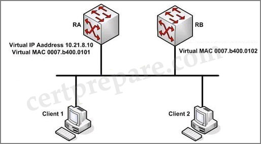
You work as a network technician at Technical Corporation. Your boss is interested in GLBP. Study the network topology exhibit carefully. Which three statements accurately describe this GLBP topology? (Choose three)

A – If RA becomes unavailable, RB will forward packets sent to the virtual MAC address of RA.
B – RA is responsible for answering ARP requests sent to the virtual IP address.
C – If another router were added to this GLBP group, there would be two backup AVGs.
D – RA alternately responds to ARP requests with different virtual MAC addresses.
Answer: A B D
Explanation
If RA fails, the GLBP protocol informs RB to replace the AVG that is down. The new AVG (in this case RB) will forward the packet sent to the 0008.b400.0101 virtual mac address, so the client sees no disruption of service nor does it need to resolve a new MAC address for the default gateway. -> A is correct.
RA, which is the AVG, replies to the ARP requests from clients with different virtual MAC addresses, thus achieving load balancing -> B is correct.
RA is elected as the AVG and RB is elected as the standby virtual gateway. If another router is added to this GLBP group, it will become a backup AVG -> there is only one backup AVG -> C is not correct.
“RA alternately responds to ARP requests with different virtual MAC addresses” this is the way GLBP provides load balancing over multiple routers (gateways) using a single virtual IP address and multiple virtual MAC addresses. Which MAC address it returns depends on which load-balancing algorithm it is configured to use -> D is correct.
↧
GLBP Questions
Here you will find answers to Gateway Load Balancing Protocol (GLBP) Questions
If you are not sure about GLBP, please read our GLBP tutorial.
Question 1
Which protocol allows for the automatic selection and simultaneous use of multiple available gateways as well as automatic failover between those gateways?
A. VRRP
B. GLBP
C. IRDP
D. HSRP
Answer: B
Explanation
In HSRP and VRRP, only the primary router is used to forward traffic, others routers must wait for the primary one down before they are used. Also, the bandwidth of the standby (and other) routers are not used and wasted. With GLBP, up to four gateways can be used simultaneously. There is still one virtual IP address in a group, but GLBP can automatically select which router in the group to forward traffic by sending the virtual MAC address of a selected router to that host.
Question 2
Which two statements are true about HSRP, VRRP, and GLBP? (Choose two)
A. GLBP and VRRP allow for MD5 authentication, whereas HSRP does not.
B. HSRP allows for multiple upstream active links being simultaneously used, whereas GLBP does not.
C. GLBP allows for router load balancing of traffic from a network segment without the different host IP configurations required to achieve the same results with HSRP.
D. Unlike HSRP and VRRP, GLBP allows automatic selection and simultaneous use of multiple available gateways.
E. GLBP allows for router load balancing of traffic from a network segment by utilizing the creation of multiple standby groups.
Answer: C D
Question 3
Refer to the exhibit. What is this configuration an example of?
| track 1 interface POS 5/0 ip routing track 2 interface POS 6/0 ip routing interface fastethernet 0/0 glbp 10 weighting 110 lower 95 upper 105 glbp 10 weighting track 1 decrement 10 glbp 10 weighting track 2 decrement 10 glbp 10 forwarder preempt delay minimum 60 |
A. GLBP weighting
B. Default AVF and AVG configuration
C. GLBP MD5 authentication
D. GLBP text authentication
E. GLBP timer manipulation
Answer: A
Explanation
The command “glbp 10 weighting 110 lower 95 upper 105″ specifies the initial weighting value (110), the lower (95) and the upper (105) thresholds. Notice that if the weight falls below the lower threshold then the router will not be an Active Virtual Forwarder (AVF) until the weight rises up to the higher threshold.
When the track object fails, the weighting is decremented by the value after the “decrement” keyword. In this case, POS5/0 and POS6/0 are tracked objects and if one of them fails, the weighting is decreased by 10 -> the weighting = 110 – 10 = 100. This value is still higher than the lower value 95 so this router is still the AVF. If both interfaces fail, the weighting will be smaller than the lower value so this router loses the AVF (until both interfaces are up again).
Question 4
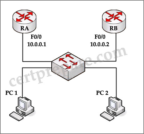
Refer to the exhibit. Which four statements accurately describe this GLBP topology? (Choose four)

A. Router A is responsible for answering ARP requests sent to the virtual IP address.
B. If Router A becomes unavailable. Router B will forward packets sent to the virtual MAC address of Router A.
C. Router A alternately responds to ARP requests with different virtual MAC addresses.
D. Router B will transition from blocking state to forwarding state when it becomes the AVG.
E. If another router were added to this GLBP group, there would be two backup AVGs.
F. Router B is in GLBP listen state.
Answer: A B C E
Explanation
In a GLBP group, the AVG assigns a virtual MAC address to each member of the GLBP group. It also answers Address Resolution Protocol (ARP) requests for the virtual IP address -> A is correct.
When Router A becomes unavailable, Router B will take over the job of forwarding packets for virtual MAC address 0007.b400.0101 of Router A -> B is correct.
Router A can load balance traffic by alternately responding to ARP requests with different virtual MAC addresses. In this case two virtual MAC addresses 0007.b400.0101 and 0007.b400.0102 will be used alternately in ARP Replies -> C is correct.
Both Router A and Router B are in forwarding state. The trick here is client 1 only sends traffic to Router A while client 2 only sends traffic to Router B -> D is not correct.
If another router were added to this GLBP group, Router B and it can forward packets in the case of Router A fails -> E is correct (but notice that the newly added router would be in listening state).
In GLBP, there are 3 states in a group: active, standby, or listen. Members of a GLBP group elect one gateway to be the Active Virtual Gateway (AVG) for that group. It also elects one member as Standby Virtual Gateway (SVG). If there are more than two members, then the members that remain are in the listen state. In this case, Router A is elected as AVG while Router B is elected as SVG -> Router B is in active state -> F is not correct.
(Reference: http://www.cisco.com/en/US/products/hw/switches/ps708/products_configuration_example09186a00807d2520.shtml)
Question 5
Exhibit:

You work as a network engineer at Certprepare.com. You study the exhibit carefully. Which GLBP device hosts receive the MAC address assignment?
A. R1
B. R2
C. The AVG
D. The AVF
Answer: D
Explanation
Notice that the MAC address of the AVF is not the physical MAC address of R1 or R2. It is a virtual MAC address used in GLBP and is used by hosts to send traffic to these routers.
Question 6
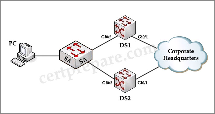
Refer to the exhibit. Host A has sent an ARP message to the default gateway IP address 10.10.10.1. Which statement is true?

A. DSw2 will reply with the IP address of the next AVF.
B. DSw1 will reply with the MAC address of the next AVF.
C. Because of the invalid timers that are configured, DSw1 will not reply.
D. DSw1 will reply with the IP address of the next AVF.
E. Because of the invalid timers that are configured, DSw2 will not reply.
F. DSw2 will reply with the MAC address of the next AVF.
Answer: F
Explanation
The priorities of two switches are equal so GLBP uses IP address of that interface to choose the AVG -> DSw2 wins the election because of higher real IP address and become the AVG. Therefore it will reply all the incoming ARP Requests with the MAC address of the next AVF (DSw1 and DSw2 alternately in this case.
Question 7
Refer to the exhibit. The Gateway Load Balancing Protocol has been configured on routers R1 and R2, and hosts A and B have been configured as shown. Which statement can be derived from the exhibit?

A. The host A default gateway has been configured as 10.88.1.10/24.
B. The GLBP weighted load balancing mode has been configured.
C. The GLBP round-robin, load-balancing mode has been configured.
D. The GLBP host-dependent, load-balancing mode has been configured.
E. The host A default gateway has been configured as 10.88.1.1/24.
F. The host A default gateway has been configured as 10.88.1.4/24.
Answer: A
Question 8
Refer to the exhibit. What is the result of setting GLBP weighting at 105 with lower threshold 90 and upper threshold 100 on this router?

A. Only if both tracked objects are up will this router will be available as an AVF for group 1.
B. Only if the state of both tracked objects goes down will this router release its status as an AVF for group 1.
C. If both tracked objects go down and then one comes up, but the other remains down, this router will be available as an AVF for group 1.
D. This configuration is incorrect and will not have any effect on GLBP operation.
E. If the state of one tracked object goes down then this router will release its status as an AVF for group 1.
Answer: B
Explanation
Each tracked object goes down will decrease the weighting of this router by 10, that makes the weighting = 105 – 10 = 95. This value is still higher than the lower threshold (90) so this router is not lost its status as an AVF. Only if both tracked objects go down, the weighting will fall below the lower threshold (105 – 10 – 10 = 85 < 90) and this router will release its status as an AVF for group 1 -> B is correct.
Question 9
Which describes the default load balancing scheme used by the Gateway Load Balancing Protocol (GLBP)?
A. Per host using a strict priority scheme
B. Per session using a round-robin scheme
C. Per session using a strict priority scheme
D. Per GLBP group using a strict priority scheme
E. Per host basis using a round robin-scheme
F. Per GLBP group using a round-robin scheme
Answer: E
Explanation
In GLBP, there are 3 operational modes for load balancing:
+ Weighted load-balancing: traffic is balanced proportional to a configured weight
+ Host-dependent load-balancing: a host is used the same virtual MAC address as long as that MAC is participating in the GLBP group.
+ Round-robin load-balancing: each virtual MAC is used to respond to each ARP Request alternately. This is also the default load balancing scheme used by GLBP.
Question 10
Refer to the exhibit. GLBP has been configured on the network. When the interface serial0/0/1 on router R1 goes down, how is the traffic coming from Host1 handled?

A. The traffic coming from Host2 is forwarded through router R2 with no disruption. The traffic from Host1 is dropped due to the disruption of the load balancing feature configured for the glbp group.
B. The traffic coming from both hosts is temporarily interrupted while the switchover to make R2 active occurs.
C. The traffic coming from Host2 is forwarded through router R2 with no disruption. Host1 sends an ARP request to resolve the MAC address for the new virtual gateway.
D. The traffic coming from Host1 and Host2 is forwarded through router R2 with no disruption.
Answer: D (?)
Explanation
When R1 goes down, the weighting is decreased by 10 by default, priority = 110 – 10 = 100 but it is still higher than the lower threshold (95) so R1 does not give up its role as a virtual forwarder and continues forwarding traffic but the Serial 0/0/1 was down so traffic from Host 1 cannot be routed. Therefore we can’t say answer D is correct.
Maybe there is something wrong in the exhibit. To make answer D correct, the weighting command should be “glbp 10 weighting 100 lower 95 upper 105″.
↧
VRRP Questions
Here you will find answers to (VRRP) Questions
Note: The main difference between HSRP and VRRP is that HSRP is a Cisco proprietary protocol while VRRP is an open standard. In VRRP, the active router is referred to as the master virtual router.
Question 1
Refer to the exhibit. Which Virtual Router Redundancy Protocol (VRRP) statement is true about the roles of the master virtual router and the backup virtual router?
A. Router A is the master virtual router, and Router B is the backup virtual router. When Router A fails, Router B will become the master virtual router. When Router A recovers, Router B will maintain the role of master virtual router.
B. Router A is the master virtual router, and Router B is the backup virtual router. When Router A fails, Router B will become the master virtual router. When Router A recovers, it will regain the master virtual router role.
C. Router B is the master virtual router, and Router A is the backup virtual router. When Router B fails, Router A will become the master virtual router. When Router B recovers, it will regain the master virtual router role.
D. Router B is the master virtual router, and Router A is the backup virtual router. When Router B fails, Router A will become the master virtual router. When Router B recovers, Router A will maintain the role of master virtual router.
Answer: B
Explanation
RouterA is the master virtual router because of higher priority value.
By default, a preemptive scheme is enabled whereby a higher priority backup virtual router that becomes available takes over for the backup virtual router that was elected to become master virtual router. You can disable this preemptive scheme using the no vrrp preempt command. If preemption is disabled, the backup virtual router that is elected to become master virtual router remains the master until the original master virtual router recovers and becomes master again.
-> B is correct.
(Reference: http://www.cisco.com/en/US/docs/ios/12_0st/12_0st18/feature/guide/st_vrrpx.html)
Question 2
Which one of the statements below correctly describes the Virtual Router Redundancy Protocol (VRRP), which is being used in the Company network to provide redundancy?
A. A VRRP group has one active and one or more standby virtual routers.
B. A VRRP group has one master and one or more backup virtual routers.
C. A VRRP group has one master and one redundant virtual router.
D. A VRRP group has one active and one backup virtual router
Answer: B
Explanation
Unilike HSRP (which has one active router, one standby router and many listening routers), a VRRP group has one master router and one or more backup routers. All backup routers are in backup state.
Question 3
Which router redundancy protocol cannot be configured for interface tracking?
A. GLBP
B. HSRP
C. RPR
D. VRRP
E. SLB
F. RPR+
Answer: D
Explanation
VRRP cannot directly track an interface status but interfaces can be tracked through a tracked object. Notice that HSRP and GLBP can track both object and interface status.
Question 4
Which protocol will enable a group of routers to form a single virtual router and will use the real IP address of a router as the gateway address?
A. Proxy ARP
B. HSRP
C. IRDP
D. VRRP
E. GLBP
Answer: D
Explanation
VRRP is similar to HSRP but. However, with VRRP the IP address used can be either a virtual one or the actual IP address of the primary router.
Note: With HSRP, two or more devices support a virtual router with a fictitious MAC address and unique IP address. Hosts use
this IP address as their default gateway.
Question 5
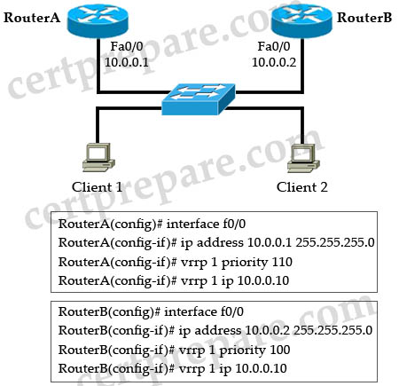
If you are a network technician, study the exhibit carefully. Which Virtual Router Redundancy Protocol (VRRP) statement is true about the roles of the master virtual router and the backup virtual router?
| RA(config)# interface f0/0 RA(config-if)# ip address 10.0.0.1 255.255.255.0 RA(config-if)# vrrp 1 priority 110 RA(config-if)# vrrp 1 ip 10.0.0.10 |
| ——————————————————————— RB(config)# interface f0/0 RB(config-if)# ip address 10.0.0.2 255.255.255.0 RB(config-if)# vrrp 1 priority 100 RB(config-if)# vrrp 1 ip 10.0.0.10 |
A – Router RA is the master virtual router, and Router RB is the backup virtual router. When Router RA fails, Router RB will become the master virtual router. When Router RA recovers, Router RB will maintain the role of master virtual router.
B – Router RA is the master virtual router, and Router RB is the backup virtual router. When Router RA fails, Router RB will become the master virtual router. When Router RA recovers, it will regain the master virtual router role.
C – Router RB is the master virtual router, and Router RA is the backup virtual router. When Router RB fails, Router RA will become the master virtual router. When Router RB recovers, RouterRA will maintain the role of master.
D – Router RB is the master virtual router, and Router RA is the backup virtual router. When Router RB fails, Router
RA will become the master virtual router. When Router RB recovers, it will regain the master virtual router role.
Answer: B
Explanation:
Router RA is the master virtual router because of its higher priority (110). By default, the pre-empting function is enabled so Router RB will become the master virtual router when RA fails; and when RA recovers, it will take the master role again.
↧
↧
HSRP Questions 5
Here you will find answers to HSRP Questions – Part 5
Question 1
You work as a network technician , study the exhibit carefully. Which two statements are true about the output from the show standby vlan 50 command? (Choose two)
| Catalyst_A# show standby vlan 50 VLAN50 – Group 1 Local State is Active, priority 200 may preempt Hellotime 3 sec, holdtime 10 sec Next hello sent in 1.302 Virtual IP address is 192.168.1.1 configured Active router is local Standby router is 192.186.1.11 expires in 9.443 Virtual MAC address is 0000.0c07.ac01 Authentication text ”AuthenKey” 2 state changes, last state change 00:11:30 IP redundancy name is “hsrp-Vl150-1″ (default)VLAN50 -Group 2 Local State is Standby , priority 100 Hellotime 3 sec, holdtime 10 sec Next hello sent in 0.98 Virtual IP address is 192.186.1.2 configured Active router is 192.168.1.11 , priority 200 expires in 6.334 Standby router is local Authentication text “AuthenKey” 3 state changes, last state change 0:09:30 IP redundancy name is “hsrp-Vl150-2″ (default) |
A. Catalyst_A is load sharing traffic in VLAN 50.
B. Hosts using the default gateway address of 192.168.1.2 will have their traffic sent to Catalyst_A.
C. The command standby 1 preempt was added to Catalyst_A.
D. Hosts using the default gateway address of 192.168.1.1 will have their traffic sent to 192.168.1.11 even after Catalyst _A becomes available again.
Answer: A C
Explanation
The output shows that the Catalyst_A switch is the active router for HSRP group 1 and the standby router for HSRP group 2 on interface VLAN 50. This means that another switch is the active router for HSRP group 2 on interface VLAN 50 -> A is correct, Catalyst_A is load sharing traffic in VLAN 50.
B is not correct, only hosts using the default gateway address of 192.168.1.1 will have their traffic sent to Catalyst_A
From the output, we notice that there is a line showing that “Local State is Active, priority 200 may preempt”. This indicates the command “standby 1 preempt” was added to Catalyst_A. If the active router (this router) fails, another router takes over its active role. The original active router is not allowed to resume the active role when it is restored until the new active router fails. Pre-empting allows a higher-priority router to take over the active role immediately.
Question 2
You are a network technician, study the exhibit carefully. Assume that Host PC can ping the Corporate Headquarters and that HSRP is configured on DS1, which is then reloaded. Assume that DS2 is then configured and reloaded. On the basis of this information, what conclusion can be drawn?
| DS1# show running-config interface Vlan10 ip address 10.10.10.2 255.255.255.0 no ip redirects standby 60 priority 105 standby 60 ip 10.10.10.1 standby 60 track GigabitEthernet 0/1 ——————————————— DS2# show running-config interface Vlan10 ip address 10.10.10.3 255.255.255.0 no ip redirects standby 60 priority 150 standby 60 ip 10.10.10.1 standby 60 track GigabitEthernet 0/1 |
A. DS1 will be the active router because it booted first.
B. DS1 will be the standby router because it has the lower IP address.
C. DS1 will be the active router because it has the lower priority configured.
D. DS2 will be the active router because it booted last.
Answer: A
Explanation
The configuration does not have the “standby 60 preempt”command so the first booted router will take the active role with any priority.
Question 3
HSRP is a Cisco-proprietary protocol developed to allow several routers (or multilayer switches) to appear as a single gateway address. Which two statements are true about the Hot Standby Router Protocol (HSRP)? (Choose two)
A – Load sharing with HSRP is achieved by creating multiple subinterfaces on the HSRP routers.
B – Routers configured for HSRP can belong to multiple groups and multiple VLANs.
C – All routers configured for HSRP load balancing must be configured with the same priority.
D – Load sharing with HSRP is achieved by creating HSRP groups on the HSRP routers.
Answer: B D
Question 4
You are a network technician, do you know which three statements are correct about a default HSRP configuration? (Choose three)
A – The Standby track interface priority is 10.
B – The Standby priority is 100.
C – The Standby hold time is 10 seconds.
D – Two HSRP groups are configured.
Answer: A B C
Question 5
Which three protocols have been developed for IP routing redundancy to protect against first-hop router failure? (Choose three)
A. GLBP
B. ICMP
C. MSTP
D. HSRP
E. VRRP
F. NHRP
Answer: A D E
Explanation
All three protocols above are used for IP routing redundancy to protect against first-hop router failure. Some main differences of them are listed below:
HSRP: is a Cisco proprietary protocol.
VRRP: Open standard, created by IETF
GLBP: is a Cisco proprietary protocol. It is the only protocol (in three) supports load-balancing.
↧
HSRP Questions 4
Here you will find answers to HSRP Questions – Part 4
Question 1
Which three of the following network features are methods used to achieve high availability? (Choose three)
A. Spanning Tree Protocol (STP)
B. Delay reduction
C. Hot Standby Routing Protocol (HSRP)
D. Dynamic routing protocols
E. Quality of Service (QoS)
F. Jitter management
Answer: A C D
Explanation
STP, HSRP and dynamic routing protocols provide backup paths to reach the destination and achieve high availability.
Note: Quality of Service (Qos) only prioritizes specific type of data over other types and provides no high availability.
Question 2
Which command will ensure that R2 will be the primary router for traffic using the gateway address of 172.16.15.20?
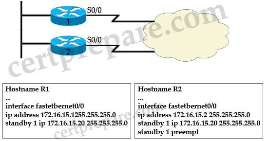
A. On R2 add the command standby 1 priority 80
B. On R1 add the command standby 1 priority 110
C. On R1 add the command standby 1 priority 80
D. On R2 remove the command standby 1 preempt
Answer: C
Explanation
By default the priority value of HSRP is 100 so in order to ensure that R2 will be the primary router for traffic using the gateway address of 172.16.15.20 we can set the priority of R2 higher than 100 or set the priority of R1 lower than 100 -> only C is correct.
Question 3
Which command will need to be added to External_A to ensure that it will take over if serial 0/0 on External_B fails?
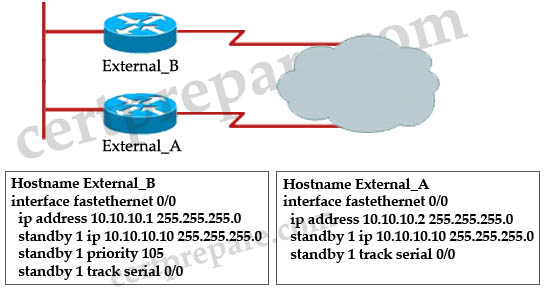
A. standby 1 priority 130
B. standby 1 preempt
C. standby 1 track fastethernet 0/0
D. standby 1 track 10.10.10.1
Answer: B
Explanation
The “standby 1 preempt” command on External_A router will make External_A take over the active state if it learns that its priority is higher than that of External_B router. In this case, when S0/0 interface of External_B fails, its priority will be 105 – 10 = 95, which is smaller than the default priority value (100) on External_A.
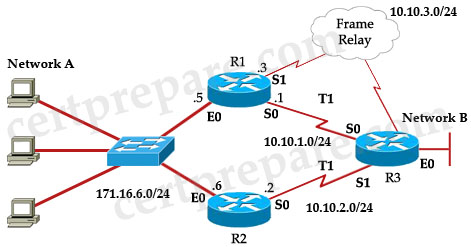
Question 4
Refer to the exhibit and the partial configuration on routers R1 and R2. Hot Standby Routing Protocol (HSRP) is configured on the network to provide network redundancy for the IP traffic. The network administrator noticed that R2 does not became active when the R1 serial0 interface goes down. What should be changed in the configuration to fix the problem?
A. The Serial0 interface on router R2 should be configured with a decrement value of 20.
B. The Serial0 interface on router R1 should be configured with a decrement value of 20.
C. R2 should be configured with a standby priority of 100.
D. R2 should be configured with a HSRP virtual address.
Answer: B
Explanation
When Serial0 of R1 goes down, the priority of R1 is still higher than that of R2 (115 – 10 = 105 > 100) so we should configured the decrement value of 20 on R1 with the command: standby 1 track Serial0 20.
Question 5
Three Cisco Catalyst switches have been configured with a first-hop redundancy protocol. While reviewing some show commands, debug output, and the syslog, you discover the following information:
| Jan 9 08:00:42.623: %STANDBY-6-STATECHANGE. Standby: 49:Vlan149 state Standby -> Active Jan 9 08:00:56.011: %STANDBY-6-STATECHANGE. Standby: 49:Vlan149 state Active -> Speak Jan 9 08:01:03.011: %STANDBY-6-STATECHANGE. Standby: 49:Vlan149 state Speak -> Standby Jan 9 08:01:29.427: %STANDBY-6-STATECHANGE. Standby: 49:Vlan149 state Standby -> Active Jan 9 08:01:36.808: %STANDBY-6-STATECHANGE. Standby: 49:Vlan149 state Active -> Speak Jan 9 08:01:43.808: %STANDBY-6-STATECHANGE. Standby: 49:Vlan149 state Speak -> Standby |
What conclusion can you infer from this information?
A. VRRP is initializing and operating correctly.
B. HSRP is initializing and operating correctly.
C. GLBP is initializing and operating correctly.
D. VRRP is not exchanging three hello messages properly.
E. HSRP is not exchanging three hello messages properly.
F. GLBP is not exchanging three hello messages properly.
Answer: E
Explanation
These error messages describe a situation in which a standby HSRP router did not receive three successive HSRP hello packets from its HSRP peer. The output shows that the standby router moves from the standby state to the active state. Shortly thereafter, the router returns to the standby state. Unless this error message occurs during the initial installation, an HSRP issue probably does not cause the error message. The error messages signify the loss of HSRP hellos between the peers. When you troubleshoot this issue, you must verify the communication between the HSRP peers. A random, momentary loss of data communication between the peers is the most common problem that results in these messages. HSRP state changes are often due to High CPU Utilization. If the error message is due to high CPU utilization, put a sniffer on the network and the trace the system that causes the high CPU utilization.
There are several possible causes for the loss of HSRP packets between the peers. The most common problems are physical layer problems, excessive network traffic caused by spanning tree issues or excessive traffic caused by each Vlan.
(Reference: http://www.cisco.com/en/US/tech/tk648/tk362/technologies_tech_note09186a0080094afd.shtml#t1)
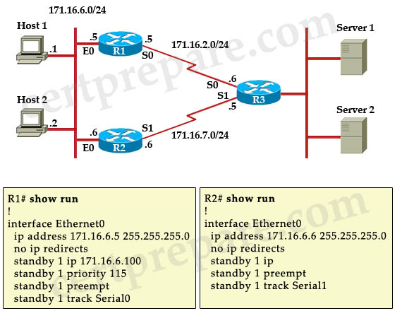
Question 6
Refer to the exhibit. Routers R1 and R2 are configured in an HSRP group to provide redundancy to the users on Network A. The T1 link between R1 and Network B has failed. How will HSRP respond to the failure?
| R1# show running-config ! interface Ethernet0 ip address 171.16.6.5 255.255.255.0 standby 1 ip 171.16.6.100 standby 1 priority 105 standby 1 preempt standby 1 track Serial0 10 standby 1 track Serial1 10 ! interface Serial0 ip address 10.10.1.1 255.255.255.0 ! interface Serial1 ip address 10.10.3.3 255.255.255.0 ! <output omitted> |
R2# show running-config ! interface Ethernet0 ip address 171.16.6.6 255.255.255.0 standby 1 ip 171.16.5 100 standby 1 preempt standby 1 track Serial0 10 ! interface Serial0 ip address 10.10.2.2 255.255.255.0 ! <output omitted> |
A. R1 will change its priority but will remain active using the Frame Relay backup link to forward the traffic to Network B
B. R2 will assume the role of active router and will use its T1 link to forward the traffic to Network B
C. Both routers R1 and R2 will be active, and the traffic will be load balanced between the T1 links
D. Both routers R1 and R2 will be inactive, and the users on Network A will lose the connectivity to Network B
Answer: B
Explanation
On R1, interface E0 is configured with the priority of 105 (standby 1 priority 105) while interface E0 of R2 uses the default priority of 100 so R1 will become the active router. Both the routers are configured with “preempt” feature so if one of them has a higher priority than the active router, it assumes control as the active router.
Both the routers are configure to track interface S0 (connected R3 via T1 links) so if its T1 links fails, the hot standby priority on the device decreases by 10 (the default decrement value). In this case if T1 link connected to R1 fails its priority would be 105 – 10 = 95 and it is smaller than that of R2 (100, by default) so R2 will take the active role and send Network A traffic via its T1 link.
Question 7
Which high availability service is verified by the show standby command?
A. VRRP
B. GLBP
C. HSRP
D. MSTP
E. PVRST
Answer: C
Explanation
The syntax for VRRP and GLBP begins with “vrrp” and “glbp” respectively, for example: “vrrp 10 priority 110″; “glbp 10 priority 254″ while the syntax for HSRP is “standby …”, for example “standby 1 ip 10.10.10.1″.
Question 8
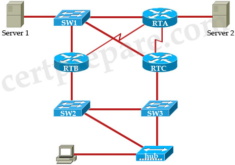
Observe the topology in the exhibit. HSRP is configured between RTB and RTC with RTC as the active router. SW2 is configured as the root bridge for the Spanning Tree Protocol. What will happen if the serial connection of RTC is down?
A. STP will not need to be recalculated because RTB will take over as active router
B. RTB and RTC will flap between active and standby because the timers for the STP are greater that the timers for HSRP
C. All traffic will automatically forward to RTB
D. SW3 will take over as the new root bridge
Answer: B
Explanation
To make the explanation easier we added port numbers to our routers and switches.
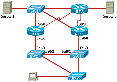
When S0/0 interface on RTC goes down, suppose RTC is tracking this interface and it is lost the active role. RTB will take the active role and turns on its Fa0/0 port. SW2 detects this link-state change and a spanning tree protocol transition takes place. The port Fa0/1 (on Sw2) takes approximately 30 seconds to go through the listening, learning, and forwarding stages. This time period exceeds the default timeouts of the HSRP hello processes so RTC, after reaching the Standby state, becomes Active because no hello packets were received from the RTB. Once again, the port Fa0/1 on Sw3 needs 30 seconds to reach final forwarding stage and that causes RTB tries to get the active role again -> Both RTB and RTC will flap between active and standby.
Note: HSRP changes its state when it fails to receive three consecutive HSRP hello packets from its peer. By default, hello timer is set to 3 seconds. That means a hello packet is sent between the HSRP standby group devices every 3 seconds, and the standby device becomes active when a hello packet has not been received for 10 seconds.(Reference: http://www.cisco.com/c/en/us/support/docs/ip/hot-standby-router-protocol-hsrp/13782-8.html)
Note: Physical link-state changes caused by HSRP state changes occur specifically on the network module-Fast Ethernet (NM-FE) interfaces on Cisco 2600, Cisco 3600 and Cisco 7200 series routers. This behavior no longer occurs in Cisco IOS® Software release 12.1(3) and higher.
Question 9
What is the maximum number of HSRP standby groups that can be configured on a Cisco router?
A. 16
B. 32
C. 64
D. 128
E. 256
Answer: E
Question 10
You have just purchased a new Cisco 3550 switch running the enhanced IOS and need to configure it to be installed in a high availability network. Which three types of interfaces can be used to configure HSRP on a 3550 EMI switch? (Choose three)
A – BVI interface
B – routed port
C – SVI interface
D – Access port
E – EtherChannel port channel
F – Loopback Interface
Answer: B C E
Explanation:
To configure HSRP, a Layer 3 interface is needed. They can be:
– Routed port: a physical port configured as a Layer 3 port by entering the no switchport interface configuration command.
– SVI: a VLAN interface created by using the interface vlan vlan_id global configuration command and by default a Layer 3 interface.
– Etherchannel port channel in Layer 3 mode: a port-channel logical interface created by using the interface port-channel port-channel-number global configuration command and binding the Ethernet interface into the channel group.
Reference:
↧
STP Questions 6
Here you will find answers to STP Questions – Part 6
Question 1
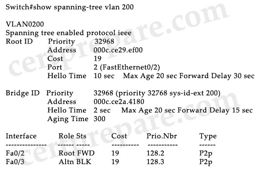
Based on the show spanning-tree vlan 200 output shown in the exhibit, which two statements about the STP process for VLAN 200 are true? (Choose two)
A. BPDUs will be sent out every two seconds.
B. The time spent in the listening state will be 30 seconds.
C. The time spent in the learning state will be 15 seconds.
D. The maximum length of time that the BPDU information will be saved is 30 seconds.
E. This switch is the root bridge for VLAN 200.
F. BPDUs will be sent out every 10 seconds.
Answer: B F
Explanation
From the output you learn that:
+ This is not the root bridge for VLAN 200 (it does not have the line “This bridge is the root” and the root bridge information is shown first. It has a Alternative port).
+ The root bridge is sending Hello every 10 seconds, Max Age is 20 seconds and Forward Delay is 15 seconds while the local bridge is sending Hello every 2 seconds, Max Age is 20 seconds and Forward Delay is 15 seconds.
Aan IEEE bridge is not concerned about the local configuration of the timers value. The IEEE bridge considers the value of the timers in the BPDU that the bridge receives. Effectively, only a timer that is configured on the root bridge of the STP is important. In this case, the local switch will import STP timers from the root bridge -> The listening state (or learning state) will be 30 seconds, which equals to Forward Delay. Also BPDUs will be sent out every 10 seconds (Hello packets).
(Reference: http://www.cisco.com/en/US/tech/tk389/tk621/technologies_tech_note09186a0080094954.shtml)
Question 2
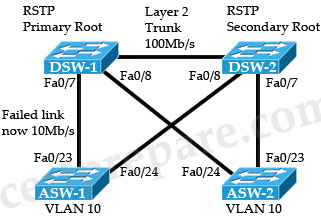
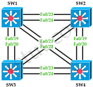
All links in this network are layer 2, fast Ethernet 100 Mb/s and operating as trunks. After a failure, the link between ASW-1 and DSW-1 has incorrectly come back up at 10 Mb/s although it is connected.
Which one of the following will occur as a result of this failure?
A. There will be no change to the forwarding path to traffic from ASW-1
B. ASW1 will block Fa0/24 in order to maintain the shortest path to the root bridge DSW-1
C. ASW-1 will block Fa0/23 in order to maintain the shortest path to the root bridge DSW-1
D. ASW-1 will elect DSW-2 as the root primary since it is close than DSW-1
Answer: C
Explanation
The picture below shows the port roles of all ports when the topology is converged after the failure.
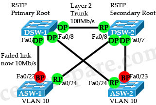
RP: Root Port
BP: Blocked Port
DP: Designated Port
Question 3
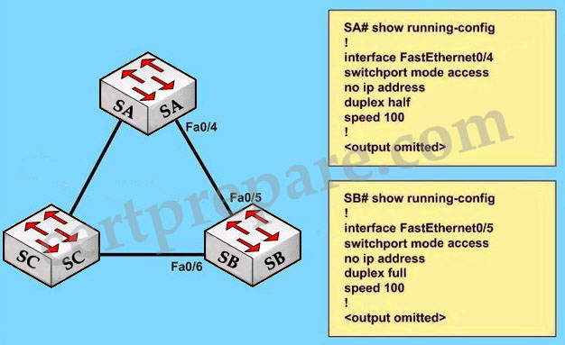
Regarding the exhibit and the partial configuration of switch SA and SB. STP is configured on all switches in the network. SB receives this error message on the console port:
00:06:34: %CDP-4-DUPLEX_MISMATCH: duplex mismatch discovered on FastEthernet0/5 (not half duplex), with SA FastEthernet0/4 (half duplex), with TBA05071417(Cat6K-B) 0/4 (half duplex).
What would be the possible outcome of the problem?
A – The root port on switch SB will fall back to full-duplex mode.
B – The interfaces between switches SA and SB will transition to a blocking state.
C – The root port on switch SA will automatically transition to full-duplex mode.
D – Interface Fa0/6 on switch SB will transit to a forwarding state and create a bridging loop.
Answer: D
Explanation:
From the output, we learned that the interfaces on two switches are operating in different duplex modes: Fa0/4 of SA in half-duplex mode & Fa0/5 of SB in full-duplex mode. In this case, because SB is operating in full duplex mode, it does not check the carrier sense before sending frames (CSMA/CD is not used in full-duplex mode). Therefore, SB can start to send frames even if SA is using the link and a collision will occur. The result of this is SA will wait a random time before attempting to transmit another frame. If B sends enough frames to A to make every frame sent from A (which includes the BPDUs) get dropped then SB can think it has lost root bridge (B does not receive BPDUs from A anymore). Therefore SB will unblock its Fa0/6 interface for transmitting and cause a bridging loop.
↧
VTP Questions 3
Here you will find answers to VTP Questions – Part 3
Question 1
Which two statements correctly describe VTP? (Choose two)
A. Transparent mode always has a configuration revision number of 0.
B. Transparent mode cannot modify a VLAN database.
C. Client mode cannot forward received VTP advertisements.
D. Client mode synchronizes its VLAN database from VTP advertisements.
E. Server mode can synchronize across VTP domains.
Answer: A D
Explanation
When setting a switch to Transparent mode, the switch’s configuration revision number is automatically reset to 0 -> A is correct.
Not only client mode but server mode synchronize its VLAN database from VTP advertisements -> D is correct.
Question 2
The network administrator needs to enable VTP pruning within the network. What action should a network administrator take to enable VTP pruning on an entire management domain?
A – enable VTP pruning on every switch in the domain
B – enable VTP pruning on any client switch in the domain
C – enable VTP pruning on any switch in the management domain
D – enable VTP pruning on a VTP server in the management domain
Answer: D
Question 3
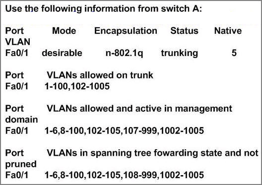
The network operations center has received a call stating that Users in VLAN 107 are unable to access resources through R1. From the information contained in the graphic, what is the cause of this problem?
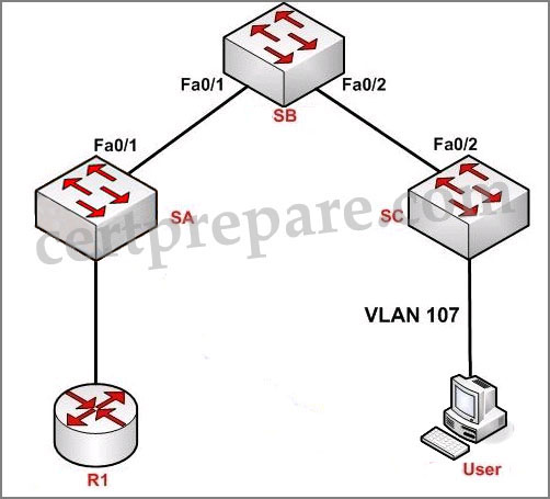
A – spanning tree is not enabled on VLAN 107
B – VTP is pruning VLAN 107
C – VLAN 107 does not exist on switch SA
D – VLAN 107 is not configured on the trunk
Answer: B
Explanation:
“VLAN allowed on trunk” – Each trunk allows all VLANs by default. However, administrator can remove or add to the list by using the “switchport trunk allowed” command.
“VLANs allowed and active in management” – To be active, a VLAN must be in this list.
“VLANs in spanning tree forwarding state and not pruned” – This list is a subset of the “allowed and active” list but with any VTP-pruned VLANs removed.
All VLANs were configured except VLAN 101 so D is not correct. VLAN 107 exists in the “allowed and active” section so A and C are not correct, too. In the “forwarding state and not pruned” we don’t see VLAN 107 so the administrator had wrongly configured this VLAN as pruned.
↧
↧
InterVLAN Routing 2
Here you will find answers to InterVLAN Routing questions – Part 2
Question 1
Refer to the exhibit.
| Switch# configure terminal Switch(config)# interface gigabitethernet0/2 Switch(config-if)# switchport autostate exclude Switch(config-if)# exit |
You have configured an interface to be an SVI for Layer 3 routing capabilities. Assuming that all VLANs have been correctly configured, what can be determined?
A. Interface gigabitethemet0/2 will be excluded from Layer 2 switching and enabled for Layer 3 routing.
B. The command switchport autostate exclude should be entered in global configuration mode, not subinterface mode, to enable a Layer 2 port to be configured for Layer 3 routing.
C. The configured port is excluded in the calculation of the status of the SVI.
D. The interface is missing IP configuration parameters; therefore, it will only function at Layer 2.
Answer: C
Explanation
An SVI is considered “up” as long as at least one port in its associated VLAN is active and forwarding. If all ports in the VLAN are down, the interface goes down to avoid creating a routing black hole. You might not want the status of a particular port (one not connected to a host) to affect the SVI’s status. The switchport autostate exclude command enables you to exclude the access ports/trunks in defining the status of the SVI (up or down) even if it belongs to the same VLAN; for example when traffic analyzers are attached to a host. They will stay up, but are just passive monitors, so if all other devices in the VLAN go down – this port would prevent the VLAN from going down, so autostate exclude is applied to allow the VLAN to still go down.
(Reference: http://www.cisco.com/en/US/docs/switches/lan/catalyst4500/12.2/37sg/configuration/guides/l3_int.html)
Question 2
Which two steps are necessary to configure inter-VLAN routing between multilayer switches? (Choose two)
A. Configure a dynamic routing protocol.
B. Configure SVI interfaces with IP addresses and subnet masks.
C. Configure access ports with network addresses.
D Configure switch ports with the autostate exclude command.
E. Document the MAC addresses of the switch ports.
Answer: A B
Explanation
A multilayer switch can use a switched virtual interface (SVI) to provide inter-VLAN routing rather than use an external router.
When we have some multilayer switches (MLS) for inter-VLAN routing we should configure a dynamic routing protocol (OSPF is currently the most popular one). For example in the topology below:

We have to configure interVLAN routing between VLAN 10 & 30 so that hosts attached to SW1 in VLAN 10 can talk to hosts attached to SW3 in VLAN 30. Of course we can use static routes but it is not recommended, especially when we add more Layer 3 Switches or more VLANs in the future.
Question 3
When configuring a routed port on a Cisco multilayer switch, which configuration task is needed to enable that port to function as a routed port?
A. Enable the switch to participate in routing updates from external devices with the router command in global configuration mode.
B. Enter the no switchport command to disable Layer 2 functionality at the interface level.
C. Each port participating in routing of Layer 3 packets must have an IP routing protocol assigned on a per-interface level.
D. Routing is enabled by default on a multilayer switch, so the port can become a Layer 3 routing interface by assigning the appropriate IP address and subnet information.
Answer: B
Question 4
Refer to the exhibit, which is from a Cisco Catalyst 3560 Series Switch.
Switch#configure terminal
Switch(config)#interface gigabitethernet0/2
Switch(config-if)#no switchport
Switch(config-if)#ip address 192.20.135.21 255.255.255.0
Switch(config-if)#no shutdown
Which statement about the Layer 3 routing functionality of the interface is true?
A. The interface is configured correctly for Layer 3 routing capabilities.
B. The interface needs an additional configuration entry to enable IP routing protocols.
C. Since the interface is connected to a host device, the spanning-tree portfast command must be added to the interface.
D. An SVI interface is needed to enable IP routing for network 192.20.135.0.
Answer: A
Question 5
Refer to the exhibit
For the configuration shown, which is the recommended method of providing inter VLAN routing?
A. Determine which switch is the root bridge then connect a router on a stick to it
B. Configure SVIs on the core switches
C. Configure SVIs on the distribution switches
D. Configure SVIs on the access layer switches
Answer: C
Explanation
Cisco recommends using layer 3 routing at the distribution layer of the multilayer switched network to terminate local VLANS, isolate network problems, and avoid access layer issues from affecting the core -> SVIs should be configured on Distribution switches.
↧
VLAN Trunking Questions 4
Here you will find answers to VLAN Trunking Questions – Part 4
Question 1
When a VLAN port configured as a trunk receives an untagged frame, what will happen?
A. The frame will be dropped
B. The frame will cause an error message to be sent
C. The frame will be processed as a native VLAN frame
D. The frame will first be tagged, then processed as a native VLAN frame
Answer: C
Question 2
Study the diagram below carefully, which three statements are true? (Choose three)
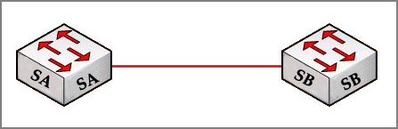
A – DTP packets are sent from Switch SB.
B – DTP is not running on Switch SA.
C – A trunk link will be formed.
D – The native VLAN for Switch SB is VLAN 1.
Answer: A C D
Explanation:
Dynamic Trunking Protocol (DTP) is the Cisco-proprietary that actively attempts to negotiate a trunk link between two switches. If an interface is set to switchport mode dynamic desirable, it will actively attempt to convert the link into trunking mode. If the peer port is configured as switchport mode trunk, dynamic desirable, or dynamic auto mode, trunking is negotiated successfully -> C is correct.
SB is in “dynamic desirable” mode so it will send DTP packets to SA to negotiate a trunk link -> A is correct.
On an 802.1Q trunk, DTP packets are sent on the native VLAN. By default, it is VLAN 1 (notice that SA’s native VLAN is 5) -> D is correct.
(Note: an 802.1Q trunk’s native VLAN is the only VLAN that has untagged frames)
Below is the switchport modes for easy reference:
| Mode | Function |
| Dynamic Auto | Creates the trunk based on the DTP request from the neighboring switch. |
| Dynamic Desirable | Communicates to the neighboring switch via DTP that the interface would like to become a trunk if the neighboring switch interface is able to become a trunk. |
| Trunk | Automatically enables trunking regardless of the state of the neighboring switch and regardless of any DTP requests sent from the neighboring switch. |
| Access | Trunking is not allowed on this port regardless of the state of the neighboring switch interface and regardless of any DTP requests sent from the neighboring switch. |
| Nonegotiate | Prevents the interface from generating DTP frames. This command can be used only when the interface switchport mode is access or trunk. You must manually configure the neighboring interface as a trunk interface to establish a trunk link. |
↧
VLAN Questions 4
Here you will find answers to VLAN Questions – Part 4
Question 1
Which three statements apply to access control of both bridged and routed traffic for VLANs? (Choose three)
A. Router ACLs can be applied to the input and output directions of a VLAN interface
B. Bridged ACLs can be applied to the input and output directions of a VLAN interface
C. Only router ACLs can be applied to a VLAN interface
D. VLAN maps can be applied to a VLAN interface
E. VLAN maps and router ACLs can be used in combination
Answer: A C E
Explanation
Bridged ACL (or VLAN Access-list, or VLAN map) is used to filter traffic that is flowing within a VLAN. It can only be applied to a VLAN, not interface -> C is correct.
An Interface VLAN (or Switch Virtual Interface – SVI) is very similar to a physical interface on a router, although it is a virtual interface only. We can apply Router ACL to the inbound and outbound direction of a VLAN interface -> A is correct.
To apply access control to both bridged and routed traffic, you can use VACLs alone or a combination of VACLs and ACLs. You can define ACLs on the VLAN interfaces to apply access control to both the ingress and egress routed traffic. You can define a VACL to apply access control to the bridged traffic. -> E is correct.
Note: In CCNA we learned about Access list, in fact it is Router Access list.
Question 2
When you create a network implementation for a VLAN solution, what is one procedure that you should include in your plan?
A. Perform an incremental implementation of components.
B. Implement the entire solution and then test end-to-end to make sure that it is performing as designed.
C. Implement trunking of all VLANs to ensure that traffic is crossing the network as needed before performing any pruning of VLANs.
D. Test the solution on the production network in off hours.
Answer: A
Explanation
Implementation Plan
+ Some examples of organizational objectives when developing a VLAN implementation plan could include: improving customer support, increasing competitiveness, and reducing costs
+ When creating a VLAN implementation plan, it is critical to have a summary implementation plan that lays out the implementation overview.
+ Incremental implementation of components is the recommended approach when defining a VLAN implementation plan.
Question 3
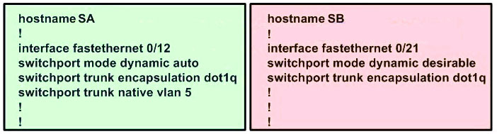
Two switches SA and SB are connected as shown below. Given the below partial configuration, which two statements are true about VLAN traffic? (Choose two)
A – VLANs 1-5 will be blocked if fa0/10 goes down.
B – VLANs 6-10 have a port priority of 128 on fa0/10.
C – VLANs 6-10 will use fa0/10 as a backup only.
D – VLANs 1-10 are configured to load share between fa0/10 and fa0/12.
Answer: C D
Explanation:
Let’s assume that SA is the root bridge for all VLANs, it will make the explanation a bit clearer…
First we should understand what will happen if nothing is configured (use default values). Because we assumed that SA is the root bridge so all of its ports will forward. SB will need to block one of its ports to avoid a bridging loop between the two switches. But how does SB select its blocked port? Well, the answer is based on the BPDUs it receives from SA. A BPDU is superior than another if it has:
1. A lower Root Bridge ID
2. A lower path cost to the Root
3. A lower Sending Bridge ID
4. A lower Sending Port ID
These four parameters are examined in order. In this specific case, all the BPDUs sent by SA have the same Root Bridge ID, the same path cost to the Root and the same Sending Bridge ID. The only parameter left to select the best one is the Sending Port ID (Port ID = port priority + port index). If using default values, the default port priority’s value is 32 or 128 (128 is much more popular today but 32 is also a default port priority’s value), so SB will compare port index values, which are unique to each port on the switch, and because Fa0/12 is inferior to Fa0/10, SB will select the port connected with Fa0/10 (of SA) as its root port and block the other port.

To change the default decision of selecting root port, we can change the port priority of each interface. The above picture is true for VLAN 1-5 because port Fa0/10 has a lower port-priority so the peer port will be chosen as the root port. For VLAN 6-10, port Fa0/12 has higher priority ID (lower port priority value) so SB will block its upper port.
For answer A – “VLANs 1-5 will be blocked if fa0/10 goes down” – is not correct because if Fa0/10 goes down, SB will unblock its lower port therefore VLANs 1-5 will still operate.
For answer B – “VLANs 6-10 have a port priority of 128 on fa0/10″ – is not always correct because VLAN 6-10 can have a different port priority (of 32) according to the Cisco’s link below.
Answer C is correct because VLAN 6-10 uses Fa0/12 link as it main path. Fa0/10 is the backup path and is only opened when port Fa0/12 fails.
Answer D is correct because this configuration provide load-balance traffic based on VLAN basis. VLANs 1-5 use Fa0/10 and VLANs 6-10 use Fa0/12 as their main paths.
Note: We can not assure the answer B is always correct so we should choose C and D if the question asks us to give only 2 choices).
Reference (and good resource, too):
http://www.cisco.com/en/US/tech/tk389/tk621/technologies_tech_note09186a00800ae96a.shtml
↧
Lab Challenge – Switch Config
Recently we posted some Lab Challenges – Switch Config on rstut.com but we think you may be interested in these switching labs so we also post the link here:
+ Lab Challenge 1: http://www.rstut.com/lab-challenge/lab-challenge-1-switch-config
+ Lab Challenge 2: http://www.rstut.com/lab-challenge/lab-challenge-2-switch-config
+ Lab Challenge 3: http://www.rstut.com/lab-challenge/lab-challenge-3-switch-config
+ Lab Challenge 4: http://www.rstut.com/lab-challenge/lab-challenge-4-switch-config
+ Lab Challenge 5: http://www.rstut.com/lab-challenge/lab-challenge-5-switch-config
We think it is very suitable for SWITCH learners to revise some knowledge about switch so please check them if you have spare time.
↧
↧
Share your SWITCH v2.0 Experience
The SWITCH 300-115 (SWITCH v2.0) exam is going to be used to replace the old SWITCH 642-813 exam so this article is devoted for candidates who took this exam sharing their experience. Please tell with us what are your materials, the way you learned, your feeling and experience after taking the SWITCH v2.0 exam…
Your posts are warmly welcome!
↧
VTPv3 Sim
You have been asked to install and configure a new switch in a customer network. Use the console access to the existing and new switches to configure and verify correct device configuration.

Question 1
You are connecting the New_Switch to the LAN topology; the switch has been partially configured and you need to complete the rest of configuration to enable PC1 communication with PC2. Which of the configuration is correct?
A. vtp domain CCNP_TEST
vtp password cisco123
vtp version 3
vtp mode server
interface e0/0
switchport mode access
switch port access vlan 100
B. vtp domain CCNP_TEST
vtp password cisco123
vtp version 3
vtp mode client
interface e0/0
switchport mode access
switchport access vlan 200
C. vtp domain CCNP_TEST
vtp password cisco123
vtp version 2
vtp mode client
interface e0/0
switchport mode access
switchport access vlan 100
D. vtp domain CCNP
vtp password cisco
vtp version 3
vtp mode client
interface e0/0
switchport mode access
switchport access vlan 100
E. vtp domain CCNP
vtp password cisco
vtp version 2
vtp mode transparent
interface e0/0
switchport mode access
switchport access vlan 200
A. Option A
B. Option B
C. Option C
D. Option D
E. Option E
Answer: D
Explanation
To comply with the configuration of other switches, we need to get VTP configuration of Sw1 or Sw2. On Sw1 use the “show vtp status” command:

From this output we learn on Sw1:
+ VTP is running version 3
+ VTP Domain is “CCNP”
+ Sw1 is the VTP Primary Server (we will explain about Primary Server later. Now just understand it is in VTP Server mode)
So on the New_Switch, the VTP Domain must match. New_Switch should run VTP version 3 if if can (but it is not a must as VTP version 2 is compatible with VTP version 3). The New_Switch is connecting to hosts so it is in Access Layer so it should be configured as a VTP Client (although Transparent mode is acceptable) so there are only two suitable choices D & E.
From the exhibit, the New_Switch is connecting to a host in VLAN 100 so its E0/0 interface should be in VLAN 100 -> only D is correct.
Question 2
Refer to the configuration. For which configured VLAN are untagged frames sent over trunk between SW1 and SW2?
A. VLAN1
B. VLAN 99
C. VLAN 999
D. VLAN 40
E. VLAN 50
F. VLAN 200
G. VLAN 300
Answer: B
Explanation
On Sw1 & Sw2 we can check with the “show interfaces trunk” command:


Sw1 & Sw2 are connected through E2/3 & E2/3 so we can see the native Vlan on these trunks are 99. We should check both Sw1 & Sw2 to see if the Native Vlan on both sides match.
Question 3
You are adding new VLANs: VLAN500 and VLAN600 to the topology in such way that you need to configure SW1 as primary root for VLAN 500 and secondary for VLAN 600 and SW2 as primary root for VLAN 600 and secondary for VLAN 500. Which configuration step is valid?
A. Configure VLAN 500 & VLAN 600 on both SW1 & SW2
B. Configure VLAN 500 and VLAN 600 on SW1 only
C. Configure VLAN 500 and VLAN 600 on SW2 only
D. Configure VLAN 500 and VLAN 600 on SW1 ,SW2 and SW4
E. On SW2; configure vtp mode as off and configure VLAN 500 and VLAN 600; configure back to vtp server mode.
Answer: B
Explanation
In VTP version 3, there are two additional fields under the output of “show vtp status” command. They are:
+ “Primary ID”: The MAC address of the Primary Server
+ “Primary Description”: The hostname of the Primary Server
The Primary Server is used on VTP version 3 to avoid the bad behavior in version 2. In VTP version 2, a VTP client (or Server) can be taken out of the network. When it comes back, it can overwrite a VTP Server if its Revision number is higher. This problem no longer exists in VTP version 3 because there is only one VTP Primary Server at a time. Only a VTP Primary Server can create new VLAN.
After creating new VLAN, the VTP Primary Server will advertise its VLAN database to other VTP clients/servers so in fact answer A is not correct. In this question you just need to check if Sw1 or Sw2 is the VTP Primary Server then we can create both VLAN 500 & 600 on it. Then it will advertise these VLANs to other switches.

From the output we see Sw1 is the Primary Server so we should configure VLAN 500 & 600 only on this switch.
Note: To make a switch a Primary Server, issue the “vtp primary vlan” under privilege exec mode. For example:
| Sw1#vtp primary vlan |
Question 4
Examine the VTP configuration. You are required to configure private VLANs for a new server deployment connecting to the SW4 switch. Which of the following configuration steps will allow creating private VLANs?
A. Disable VTP pruning on SW1 only
B. Disable VTP pruning on SW2 only
C. Disable VTP pruning on SW4 only
D. Disable VTP pruning on SW2, SW4 and New_Switch
E. Disable VTP pruning on New_Switch and SW4 only.
Answer: C
Explanation
To configure private VLAN we have to change VTP (even version 3) to Transparent mode. In fact, to disable VTP pruning on Sw4 (in Client mode) we also have to change to VTP Transparent mode so answer C can be understood as “change SW4 to Transparent mode” so it is the best choice.
↧
Miscellaneous Questions
Question 1
What is the function of NSF?
A. forward traffic simultaneously using both supervisors
B. forward traffic based on Cisco Express Forwarding
C. provide automatic failover to back up supervisor in VSS mode
D. provide nonstop forwarding in the event of failure of one of the member supervisors
Answer: D
Explanation
Nonstop Forwarding (NSF) works with Stateful switchover (SSO) to minimize the amount of time a network is unavailable to its users following a switchover. The main objective of Cisco NSF is to continue forwarding IP packets following a route processor (RP) switchover.
Usually, when a networking device restarts, all routing peers of that device detect that the device went down and then came back up. This transition results in what is called a routing flap, which could spread across multiple routing domains. Routing flaps caused by routing restarts create routing instabilities, which are detrimental to the overall network performance. Cisco NSF helps to suppress routing flaps in SSO-enabled devices, thus reducing network instability.
Cisco NSF allows for the forwarding of data packets to continue along known routes while the routing protocol information is being restored following a switchover. With Cisco NSF, peer networking devices do not experience routing flaps. Data traffic is forwarded through intelligent line cards while the standby RP assumes control from the failed active RP during a switchover. The ability of line cards to remain up through a switchover and to be kept current with the Forwarding Information Base (FIB) on the active RP is key to Cisco NSF operation.
Question 2
Which statement describes what happens if all VSL connections between the virtual switch members are lost?
A. Both virtual switch members cease to forward traffic.
B. The VSS transitions to the dual active recovery mode, and both virtual switch members continue to forward traffic independently.
C. The virtual switch members reload.
D. The VSS transitions to the dual active recovery mode, and only the new active virtual switch continues to forward traffic.
Answer: D
Explanation
VSLs can be configured with up to eight links between the two switches across any combination of line cards or supervisor ports to provide a high level of redundancy. If for some rare reason all Virtual Switching Link (VSL) connections are lost between the virtual switch members leaving both the virtual switch members up, the VSS will transition to the dual active recovery mode.
In the dual active recovery mode, all interfaces except the VSL interfaces are in an operationally shut down state in the formerly active virtual switch member. The new active virtual switch continues to forward traffic on all links.
Question 3
Which statement describes what happens when a switch enters dual active recovery mode?
A. The switch shuts down and waits for the VSL link to be restored before sending traffic.
B. All interfaces are shut down in the formerly active virtual switch member, but the new active virtual switch forwards traffic on all links.
C. The switch continues to forward traffic out all links and enables spanning tree on VSL link and all other links to prevent loops.
D. The VSS detects which system was last in active state and shuts down the other switch.
Answer: B
Explanation
If for some rare reason all Virtual Switching Link (VSL) connections are lost between the virtual switch members leaving both the virtual switch members up, the VSS will transition to the dual active recovery mode.
In the dual active recovery mode, all interfaces except the VSL interfaces are in an operationally shut down state in the formerly active virtual switch member. The new active virtual switch continues to forward traffic on all links.
Question 4
Which option is a benefit of using VSS?
A. reduces cost
B. simplifies configuration
C. provides two independent supervisors with two different control planes
D. removes the need for a First Hop Redundancy Protocol
Answer: D
Explanation
VSS increases operational efficiency by simplifying the network, reducing switch management overhead by at least 50 percent. This includes removing the need for Hot Standby Router Protocol (HSRP), Virtual Router Redundancy Protocol (VRRP), and Gateway Load Balancing Protocol (GLBP) -> D is correct.
↧
StackWise Questions
Question 1
What is the maximum number of switches that can be stacked using Cisco StackWise?
A. 4
B. 5
C. 8
D. 9
E. 10
F. 13
Answer: D
Explanation
The switches are united into a single logical unit using special stack interconnect cables that create a bidirectional closed-loop path. This bidirectional path acts as a switch fabric for all the connected switches. Network topology and routing information is updated continuously through the stack interconnect. All stack members have full access to the stack interconnect bandwidth. The stack is managed as a single unit by a master switch, which is elected from one of the stack member switches.
Each switch in the stack has the capability to behave as a master or subordinate (member) in the hierarchy. The master switch is elected and serves as the control center for the stack. Both the master member switches act as forwarding processors. Each switch is assigned a number. Up to nine separate switches can be joined together. The stack can have switches added and removed without affecting stack performance.
Question 2
A network engineer wants to add a new switch to an existing switch stack. Which configuration must be added to the new switch before it can be added to the switch stack?
A. No configuration must be added.
B. stack ID
C. IP address
D. VLAN information
E. VTP information
Answer: A
Explanation
When we add a new switch to an existing switch stack, the election will take place automatically to choose a master switch. We don’t have to configure anything on the newly added switch. In the case you want the newly added switch to become the master, use this command then reload it:
| switch(config)# switch 1 priority 15 |
Note: Turn off the switch before connecting the stackwise cables. Only turn it on after finishing connecting stackwise cables.
Question 3
What percentage of bandwidth is reduced when a stack cable is broken?
A. 0
B. 25
C. 50
D. 75
E. 100
Answer: C
Explanation
The picture below shows how StackWise cables are connected between switches:

When the stackwise cables are fully connected (as shown above), the stack ring speed is 32Gbps full-duplex. To efficiently load balance the traffic, the stackwise cables function bi-directionally with two 16 Gbps counter-rotating rings. It means packets are allocated between two logical counter-rotating paths. Each counter-rotating path supports 16 Gbps in both directions, yielding a traffic total of 32 Gbps bidirectionally.
A break in any one of the cables will result in the stack bandwidth being reduced to half (16 Gbps) of its full capacity.
↧
↧
SDM Questions
Question 1
Which statement about the use of SDM templates in a Cisco switch is true?
A. SDM templates are used to configure system resources in the switch to optimize support for specific features, depending on how the switch is used in the network.
B. SDM templates are used to create Layer 3 interfaces (switch virtual interfaces) to permit hosts in one VLAN to communicate with hosts in another VLAN.
C. SDM templates are used to configure ACLs that protect networks and specific hosts from unnecessary or unwanted traffic.
D. SDM templates are used to configure a set of ACLs that allows the users to manage the flow of traffic handled by the route processor.
E. SDM templates are configured by accessing the switch using the web interface.
Answer: A
Explanation
SDM templates are used to configure system resources in the switch to optimize support for specific features, depending on how the switch is used in the network. You can select a template to provide maximum system usage for some functions or use the default template to balance resources.
To allocate ternary content addressable memory (TCAM) resources for different usages, the switch SDM templates prioritize system resources to optimize support for certain features. You can select SDM templates to optimize these features:
+ Access – The access template maximizes system resources for access control lists (ACLs) to accommodate a large number of ACLs.
+ Default – The default template gives balance to all functions.
+ Routing – The routing template maximizes system resources for IPv4 unicast routing, typically required for a router or aggregator in the center of a network.
+ VLANs – The VLAN template disables routing and supports the maximum number of unicast MAC addresses. It would typically be selected for a Layer 2 switch.
In addition, the dual IPv4 and IPv6 templates enable a dual stack environment.
Question 2
Which SDM template disables routing and supports the maximum number of unicast MAC addresses?
A. VLAN
B. access
C. default
D. routing
Answer: A
Explanation
The VLAN template disables routing and supports the maximum number of unicast MAC addresses. It would typically be selected for a Layer 2 switch.
Question 3
Which SDM template is the most appropriate for a Layer 2 switch that provides connectivity to a large number of clients?
A. VLAN
B. default
C. access
D. routing
Answer: A
Explanation
The VLAN template disables routing and supports the maximum number of unicast MAC addresses. It would typically be selected for a Layer 2 switch.
Question 4
A network engineer deployed a switch that operates the LAN base feature set and decides to use the SDM VLAN template. The SDM template is causing the CPU of the switch to spike during peak working hours. What is the root cause of this issue?
A. The VLAN receives additional frames from neighboring switches.
B. The SDM VLAN template causes the MAC address-table to overflow.
C. The VLAN template disables routing in hardware.
D. The switch needs to be rebooted before the SDM template takes effect.
Answer: C
Explanation
The VLAN template disables routing and supports the maximum number of unicast MAC addresses. It would typically be selected for a Layer 2 switch.
↧
UDLD Questions
Question 1
Which statement about the UDLD protocol is true?
A. UDLD is a Cisco-proprietary Layer 2 protocol that enables devices to monitor the physical status of links and detect unidirectional failures.
B. UDLD is a Cisco-proprietary Layer 2 protocol that enables devices to advertise their identity, capabilities, and neighbors on a local area network.
C. UDLD is a standardized Layer 2 protocol that enables devices to monitor the physical status of links and detect unidirectional failures.
D. UDLD is a standardized Layer 2 protocol that enables devices to advertise their identity, capabilities, and neighbors on a local area network.
Answer: A
Explanation
UDLD is a Layer 2 protocol that enables devices connected through fiber-optic or twisted-pair Ethernet cables to monitor the physical configuration of the cables and detect when a unidirectional link exists. All connected devices must support UDLD for the protocol to successfully identify and disable unidirectional links. When UDLD detects a unidirectional link, it administratively shuts down the affected port and alerts you. Unidirectional links can cause a variety of problems, including spanning-tree topology loops.
Question 2
Which option lists the modes that are available for configuring UDLD on a Cisco switch?
A. normal and aggressive
B. active and aggressive
C. normal and active
D. normal and passive
E. normal and standby
Answer: A
Explanation
A unidirectional link occurs whenever traffic sent by a local device is received by its neighbor but traffic from the neighbor is not received by the local device.
UDLD supports two modes of operation: normal (the default) and aggressive. In normal mode, UDLD can detect unidirectional links due to misconnected interfaces on fiber-optic connections. In aggressive mode, UDLD can also detect unidirectional links due to one-way traffic on fiber-optic and twisted-pair links and to misconnected interfaces on fiber-optic links.
Question 3
While working in the core network building, a technician accidently bumps the fiber connection between two core switches and damages one of the pairs of fiber. As designed, the link was placed into a non-forwarding state due to a fault with UDLD. After the damaged cable was replaced, the link did not recover. What solution allows the network switch to automatically recover from such an issue?
A. macros
B. errdisable autorecovery
C. IP Event Dampening
D. command aliases
E. Bidirectional Forwarding Detection
Answer: B
Explanation
When unidirectional link occurs, UDLD can put that port into errdisable state (same as shutdown). The administrator must manually shut/no shut to bring that interface up. If we want the interface to automatically recover then configure the “errdisable autorecovery”. For example:
| errdisable recovery cause udld errdisable recovery interval 30 |
By doing so, the port will be place back in up state (no err-disabled state) after 30 seconds, if the port still has violation it will be placed again in “err-disabled” state, otherwise it will remain in up state.
Question 4
After UDLD is implemented, a Network Administrator noticed that one port stops receiving UDLD packets. This port continues to reestablish until after eight failed retries. The port then transitions into the errdisable state. Which option describes what causes the port to go into the errdisable state?
A. Normal UDLD operations that prevent traffic loops.
B. UDLD port is configured in aggressive mode.
C. UDLD is enabled globally.
D. UDLD timers are inconsistent.
Answer: B
Explanation
UDLD aggressive mode is disabled by default. Configure UDLD aggressive mode only on point-to-point links between network devices that support UDLD aggressive mode. With UDLD aggressive mode enabled, when a port on a bidirectional link that has a UDLD neighbor relationship established stops receiving UDLD packets, UDLD tries to reestablish the connection with the neighbor. After eight failed retries, the port is disabled.
Question 5
After reviewing UDLD status on switch ports, an engineer notices that the switch LEDs are green. Which statement describes what this indicates about the status of the port?
A. The port is fully operational and no known issues are detected.
B. The bidirectional status of “unknown” indicates that the port will go into the disabled state because it stopped receiving UDLD packets from its neighbor.
C. UDLD moved into aggressive mode after inconsistent acknowledgements were detected.
D. The UDLD port is placed in the “unknown” state for 5 seconds until the next UDLD packet is received on the interface.
Answer: A
↧
DHCP Snooping
Quick review of DHCP Spoofing:
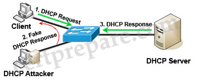
DHCP spoofing is a type of attack in that the attacker listens for DHCP Requests from clients and answers them with fake DHCP Response before the authorized DHCP Response comes to the clients. The fake DHCP Response often gives its IP address as the client default gateway -> all the traffic sent from the client will go through the attacker computer, the attacker becomes a “man-in-the-middle”.
The attacker can have some ways to make sure its fake DHCP Response arrives first. In fact, if the attacker is “closer” than the DHCP Server then he doesn’t need to do anything. Or he can DoS the DHCP Server so that it can’t send the DHCP Response.
DHCP snooping can prevent DHCP spoofing attacks. DHCP snooping is a Cisco Catalyst feature that determines which switch ports can respond to DHCP requests. Ports are identified as trusted and untrusted.

Only ports that connect to an authorized DHCP server are trusted, and allowed to send all types of DHCP messages. All other ports on the switch are untrusted and can send only DHCP requests. If a DHCP response is seen on an untrusted port, the port is shut down.
Question 1
A Cisco Catalyst switch that is prone to reboots continues to rebuild the DHCP snooping database. What is the solution to avoid the snooping database from being rebuilt after every device reboot?
A. A DHCP snooping database agent should be configured.
B. Enable DHCP snooping for all VLANs that are associated with the switch.
C. Disable Option 82 for DHCP data insertion.
D. Use IP Source Guard to protect the DHCP binding table entries from being lost upon rebooting.
E. Apply ip dhcp snooping trust on all interfaces with dynamic addresses.
Answer: A
Explanation
To retain the bindings across switch reloads, you must use the DHCP snooping database agent. Without this agent, the bindings established by DHCP snooping are lost upon switch reload. Connectivity is lost as well.
Question 2
A server with a statically assigned IP address is attached to a switch that is provisioned for DHCP snooping. For more protection against malicious attacks, the network team is considering enabling dynamic ARP inspection alongside DHCP snooping. Which solution ensures that the server maintains network reachability in the future?
A. Disable DHCP snooping information option.
B. Configure a static DHCP snooping binding entry on the switch.
C. Trust the interface that is connected to the server with the ip dhcp snooping trust command.
D. Verify the source MAC address of all untrusted interfaces with ip dhcp snooping verify mac-address command.
Answer: B
Explanation
Static DHCP snooping binding defines a mapping between a fixed IP address and the client’s MAC address. Each entry in the DHCP snooping binding database includes the MAC address of the host, the leased IP address, the lease time, the binding type, and the VLAN number and interface information associated with the host. This is how to configure a static DHCP snooping binding entry:
| Switch#ip dhcp snooping binding mac-address vlan vlan-id ip-address interface interface expiry seconds |
Question 3
DHCP snooping and IP Source Guard have been configured on a switch that connects to several client workstations. The IP address of one of the workstations does not match any entries found in the DHCP binding database. Which statement describes the outcome of this scenario?
A. Packets from the workstation will be rate limited according to the default values set on the switch.
B. The interface that is connected to the workstation in question will be put into the errdisabled state.
C. Traffic will pass accordingly after the new IP address is populated into the binding database.
D. The packets originating from the workstation are assumed to be spoofed and will be discarded.
Answer: D
Explanation
IP Source Guard provides source IP address filtering on a Layer 2 port to prevent a malicious host from impersonating a legitimate host by assuming the legitimate host’s IP address. The feature uses dynamic DHCP snooping and static IP source binding to match IP addresses to hosts on untrusted Layer 2 access ports.
Initially, all IP traffic on the protected port is blocked except for DHCP packets. After a client receives an IP address from the DHCP server, or after static IP source binding is configured by the administrator, all traffic with that IP source address is permitted from that client. Traffic from other hosts is denied. This filtering limits a host’s ability to attack the network by claiming a neighbor host’s IP address.
Therefore if the switch receives a packet that does not match any entries found in the DHCP binding database, that packet is assumed to be spoofed and will be discarded.
Question 4
A DHCP configured router is connected directly to a switch that has been provisioned with DHCP snooping. IP Source Guard with the ip verify source port-security command is configured under the interfaces that connect to all DHCP clients on the switch. However, clients are not receiving an IP address via the DHCP server.
Which option is the cause of this issue?
A. The DHCP server does not support information option 82.
B. The DHCP client interfaces have storm control configured.
C. Static DHCP bindings are not configured on the switch.
D. DHCP snooping must be enabled on all VLANs, even if they are not utilized for dynamic address allocation.
Answer: A
Explanation
The command “ip verify source port-security” enables IP source guard with source IP and MAC address filtering. When using this command, there are two caveats:
+ The DHCP server must support option 82, or the client is not assigned an IP address.
+ The MAC address in the DHCP packet is not learned as a secure address. The MAC address of the DHCP client is learned as a secure address only when the switch receives non-DHCP data traffic.
Question 5
A switch is added into the production network to increase port capacity. A network engineer is configuring the switch for DHCP snooping and IP Source Guard, but is unable to configure ip verify source under several of the interfaces. Which option is the cause of the problem?
A. The local DHCP server is disabled prior to enabling IP Source Guard.
B. The interfaces are configured as Layer 3 using the no switchport command.
C. No VLANs exist on the switch and/or the switch is configured in VTP transparent mode.
D. The switch is configured for sdm prefer routing as the switched database management template.
E. The configured SVIs on the switch have been removed for the associated interfaces.
Answer: B
Explanation
The following restrictions apply to IP source guard:
+ Supported only on ingress Layer 2 ports (including access and trunk ports)
+ Supported only in hardware; not applied to any traffic that is processed in software.
+ Does not support filtering of traffic based on MAC address.
+ Is not supported on private VLANs.
Question 6
Which type of information does the DHCP snooping binding database contain?
A. untrusted hosts with leased IP addresses
B. trusted hosts with leased IP addresses
C. untrusted hosts with available IP addresses
D. trusted hosts with available IP addresses
Answer: A
Explanation
The DHCP snooping binding database contains information about untrusted hosts with leased IP addresses. Each entry in the DHCP snooping binding database includes the MAC address of the host, the leased IP address, the lease time, the binding type, the VLAN number and interface information associated with the host.
Question 7
Which command is needed to enable DHCP snooping if a switchport is connected to a DHCP server?
A. ip dhcp snooping trust
B. ip dhcp snooping
C. ip dhcp trust
D. ip dhcp snooping information
Answer: A
Explanation
The port connected to a DHCP server should be configured as trusted port with the “ip dhcp snooping trust” command. Other ports connecting to hosts are untrusted ports by default.
Question 8
Which database is used to determine the validity of an ARP packet based on a valid IP-to-MAC address binding?
A. DHCP snooping database
B. dynamic ARP database
C. dynamic routing database
D. static ARP database
Answer: A
Explanation
DHCP snooping database contains MAC address-to-IP address bindings which Dynamic ARP Inspection (DAI) uses to determine the validity of an ARP packet.
Question 9
When IP Source Guard with source IP filtering is enabled on an interface, which feature must be enabled on the access VLAN for that interface?
A. DHCP snooping
B. storm control
C. spanning-tree portfast
D. private VLAN
Answer: A
Explanation
When IP Source Guard with source IP filtering is enabled on an untrusted interface, DHCP snooping must be enabled because it filters traffic based on IP information stored in the corresponding DHCP binding table entry.
Question 10
Which switch feature determines validity based on IP-to-MAC address bindings that are stored in a trusted database?
A. Dynamic ARP Inspection
B. storm control
C. VTP pruning
D. DHCP snooping
Answer: A
Explanation
The function of DAI is:
+ Intercepts all ARP requests and responses on untrusted ports
+ Verifies that each of these intercepted packets has a valid IP-to-MAC address binding before updating the local ARP cache or before forwarding the packet to the appropriate destination
+ Drops invalid ARP packets
On untrusted ports, the switch captures all ARP packets (both request and reply) and then validates the Source Protocol and Source Hardware address values against the snooping table database for that port.
If the MAC address and IP address and the corresponding port do not match the snooping database entry, the ARP packets are dropped. DAI thus prevents the node from specifying a non-legitimate IP-MAC address binding which differs from what was given by the DHCP server.
↧